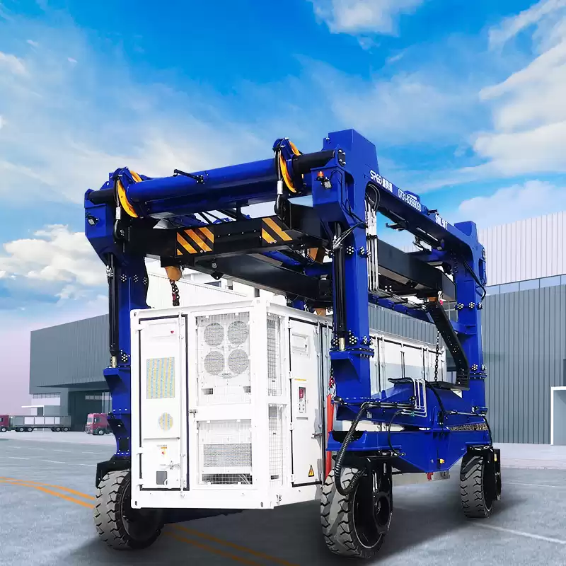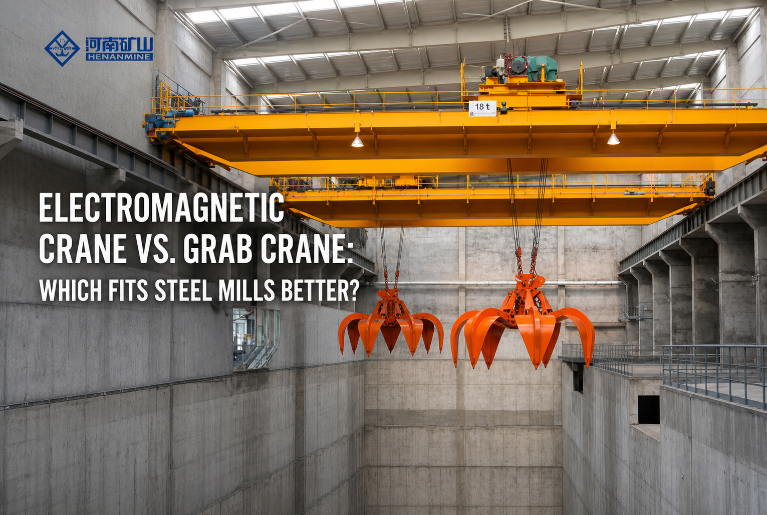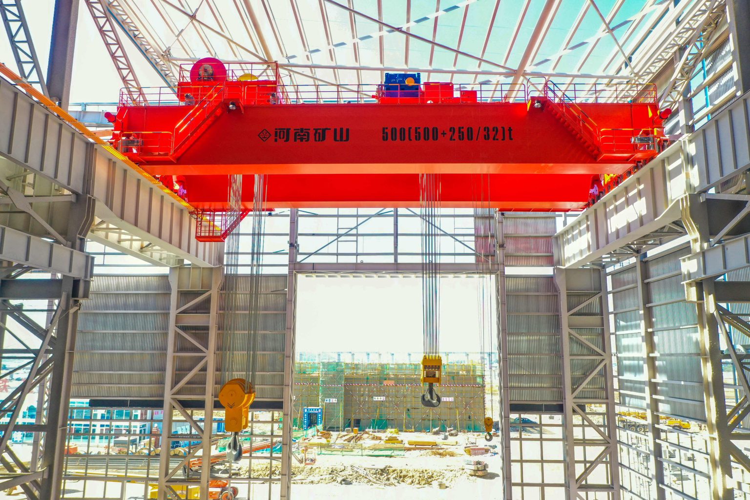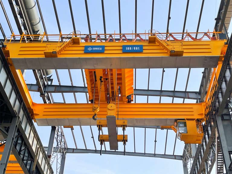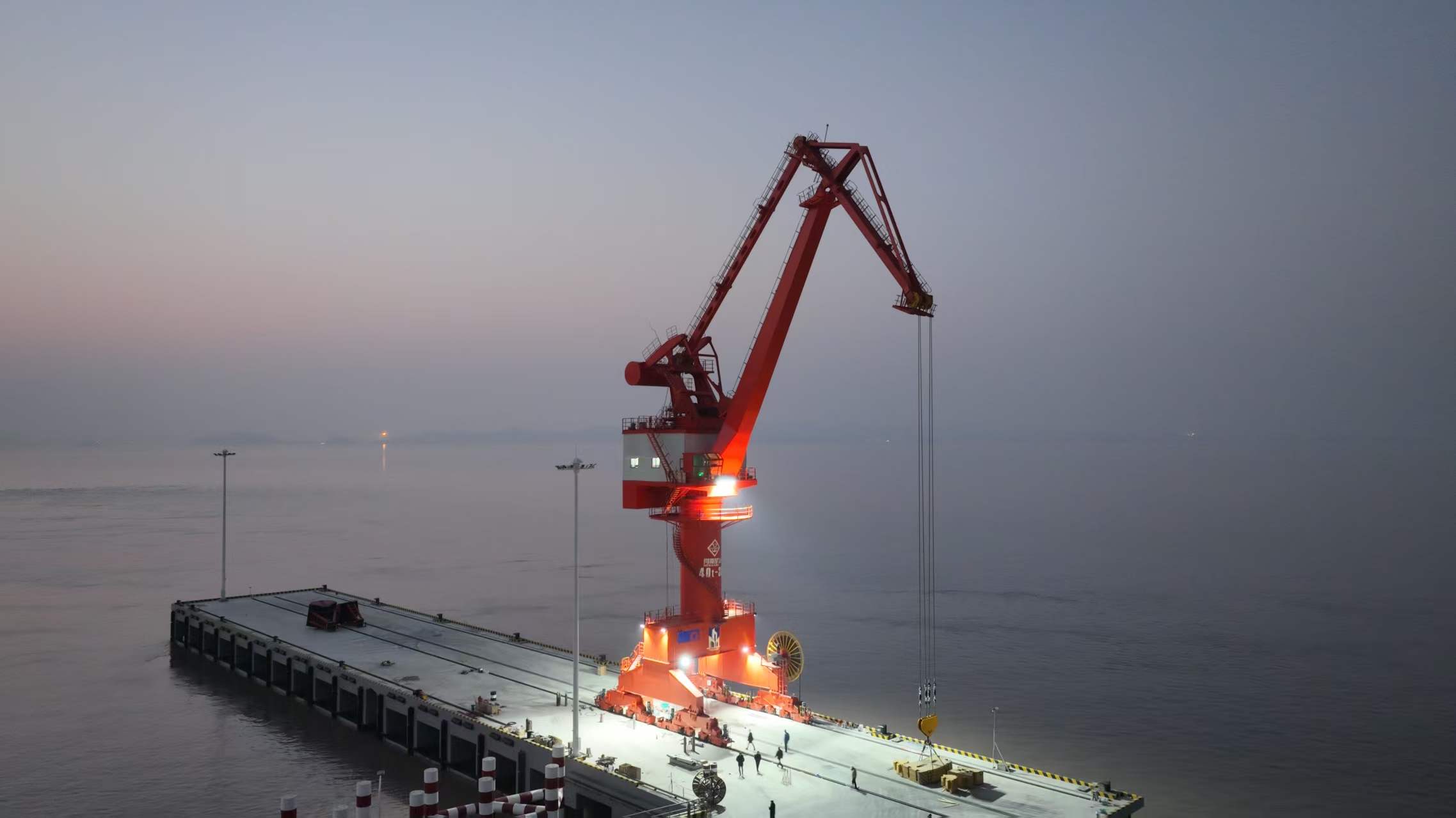

Tunneling & Underground Excavation Gantry Cranes: High-Lift Shaft Winch Systems
In the construction of underground infrastructure, muck removal, material transportation, and equipment hoisting are the keys to controlling the construction progress.The gantry crane is equipped with a high-lifting shaft winch system, which is suitable for complex working conditions of deep wells and deep tunnels. With the advantages of high efficiency, safety and strong adaptability, it is widely used in various underground excavation projects.
This article focuses on the core equipment of shaft winch system, high-lift shaft winch, and tunnel gantry crane, and comprehensively analyzes its definition, working principle, structural configuration, application scenarios, selection standards, safety protection, and operation and maintenance points, and provides professional reference for equipment selection, construction operation and maintenance, and program customization for underground excavation projects.
What Is a Tunneling & Underground Excavation Gantry Crane
Tunnel and underground excavation gantry cranes are special ground lifting equipment suitable for vertical operation of shafts. They can vertically lift heavy loads such as muck, building materials, prefabricated components, and construction machinery. They are widely used in tunnels, subways, water conservancy, mines, and underground municipal projects.
Unlike the horizontal operation design of ordinary gantry cranes, this equipment mainly focuses on large-depth, high-frequency continuous vertical lifting. The gantry is straddled at the wellhead of the shaft. As the core carrying base of the high-lifting shaft winch system, it can be stably adapted to ultra-deep well operations from tens of meters to 200 meters. It is the core special equipment for deep shaft construction.
Integrated principle of high-lift shaft winch
The complete lifting system adopts the integrated design of "gantry bearing + winch drive", and each performs its own duties and works together to form a complete vertical lifting system for shafts.:
- Main body of the gantry: As the main rigid bearing structure of the system, it is straddled above the wellhead of the shaft to provide a stable installation foundation for winches, pulleys and safety components, accurately locate the vertical center of the rope, and effectively avoid the lateral partial load force.;
- High-lifting shaft winch: The power core of the complete set of equipment, equipped with a large-capacity rope multi-layer winding reel, which can store 100-meter-long wire rope, relying on frequency conversion and speed regulation technology, to achieve stable and accurate lifting power output under deep well conditions.;
- Rope pulley system: responsible for load force conduction and vertical guidance, greatly reducing the friction loss of wire rope, ensuring the vertical and smooth operation of the material spreader throughout the process, and improving the transmission efficiency of the whole machine;
- Electronic control and safety system: real-time monitoring of the operating status of all working conditions, integrated speed adjustment, overload protection, emergency braking and fault interlocking functions, to ensure that every lifting operation is safe, controllable, stable and reliable.
Core components of the system
A complete set of tunnel shaft gantry lifting system, including seven core components, is indispensable:
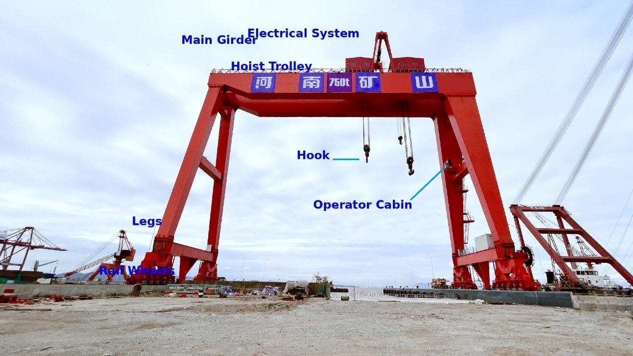
- Gantry frame: it is made of welded steel box girders or I-beams, which carry all operating loads and span the wellhead. It is the structural foundation of the entire set of equipment, and its stability directly determines the safety of the operation.
- Lifting machinery mechanism: it includes a special drive motor, reducer, brake device, and reel assembly to provide power support for load lifting and is suitable for continuous heavy-duty operations.
- Shaft winch: The core equipment of the system, large-diameter multi-layer winding reel can accommodate ultra-long wire ropes, with a frequency conversion drive system to achieve controllable speed regulation, equipped with redundant braking structure, suitable for deep well high-lifting operations.
- Wire rope and pulley block: special wire rope with anti-rotation, high fatigue and high strength is used to adapt to deep well self-weight loads; customized pulley blocks optimize rope guidance to reduce wear and improve mechanical efficiency.
- Lifting hopper/manned cage: end load-carrying device, the hopper is used to clear muck and transport building materials; special manned cage is used for personnel lifting, and it needs to be equipped with a dedicated safety protection structure. It is strictly prohibited to replace the material bucket.
- Electrical control system: it consists of a main power distribution cabinet, a frequency conversion drive device, an operation console, a PLC programmable controller, and a working condition monitoring instrument to achieve accurate monitoring and adjustment of speed, load, and depth.
- Safety emergency system: it includes overload limiter, upper and lower limit protection, emergency braking, rope monitoring, fault interlocking and other devices to avoid the safety risks of deep well operations in all directions.
How High-Lift Shaft Winch Systems Work
Layout design of door frame and shaft
The gantry crane is precisely erected directly above the wellhead of the vertical well, and the outriggers are fixed to the special foundation on both sides of the wellhead. The span of the gantry completely covers the wellhead and reserves sufficient working space.The layout of the equipment strictly plans the load transfer path and the vertical lifting area, and the falling point of the pulley rope must be accurately aligned with the center of the shaft and the center of the hopper guidance system.
The precise layout design can avoid the ropes and the side walls of the well from being subjected to lateral tension, effectively reduce equipment wear, avoid the risk of load offset, and ensure the stability of full-depth operations. It is the basic prerequisite for deep well lifting operations.
Lifting operation process
The complete set of operation cycle processes is standardized and automated to meet the needs of continuous construction:
The first step: The bottom loading of the well, the underground construction personnel will load the muck, building materials and construction equipment into the hopper in a regular manner, and connect with the ground operator through a dedicated communication system to confirm, complete the pre-operation preparation, and start the lifting process.
The second step: the vertical lifting and transportation frequency conversion drive system starts smoothly, driving the winch reel to collect the rope, and the fully loaded hopper rises vertically at a uniform speed; when approaching the wellhead, it automatically slows down and slows down, accurately completing the wellhead alignment to ensure that the lifting process is smooth and impact-free.
The third step: After the material unloading of the controllable decentralization operation is completed, the empty bucket will be smoothly decentralized at a set speed.Relying on frequency conversion speed regulation and redundant braking system, the risk of air bucket falling is completely eliminated, and problems such as deep well rope shaking and load shaking are effectively avoided.
The fourth step: Unloading and cycle reset. The wellhead hopper unloads the material to the silo, conveyor belt or transportation vehicle. After completing a single operation cycle, it is quickly reset and enters the next cycle of operation.The efficiency of equipment cycle operation directly determines the overall excavation and construction progress of the shaft.
Key points of rope wheel and reel configuration
- Deep well wire rope selection core deep well operation wire rope cannot choose ordinary models, and must meet four core standards: 6:1 and above safety breaking coefficient, anti-rotation structure to prevent hopper shaking, high fatigue resistance, adapt to high-frequency bending, take into account the weight and carrying strength of the deep well rope, to avoid the weight of the deep well rope affecting the rated load.
- Reel capacity design The reel needs to accommodate all the wire ropes corresponding to the maximum depth of the shaft, and at the same time reserve a safety dead rope ring to prevent the rope from falling off.Multi-layer winding of deep wells will change the effective radius of the reel. The torque change needs to be accurately calculated during the equipment design stage, and the parameters of the motor and reducer need to be matched to ensure the stability of the full-depth operation power.
- The pulley block is equipped with a standard top pulley diameter and wire rope diameter ratio of not less than 20:1 to minimize the bending stress of the rope; it is equipped with high-strength wear-resistant bearings, suitable for 24-hour continuous operation, and adopts a single-rope or double-rope winding structure according to the load requirements to balance the bearing capacity and operating efficiency.
Load control and positioning technology
Modern high-lifting shaft winch systems are equipped with frequency conversion speed control systems to achieve precise control of all working conditions:
The multi-gear variable speed mode is adopted to improve the guarantee efficiency at high speed in the middle of the deep well, and the low-speed creep mode is used at the wellhead and bottom to ensure accurate alignment; the system is equipped with a programmable acceleration and deceleration curve to eliminate rope impact and load swing caused by sudden start and stop, and extend the service life of the equipment.
At the same time, the depth of the shaft is monitored in real time through encoders and depth monitors, the wellhead and bottom operating areas are automatically identified, and the deceleration and precise shutdown are slowed down in advance, which is suitable for the dynamic construction scene of deep excavation of the shaft layer by layer.
Key Applications in Tunneling & Underground Excavation
The tunnel gantry crane and shaft winch system are adapted to various complex underground infrastructure conditions. With the advantages of large depth, heavy load and continuous operation, they have become the core supporting equipment for underground engineering construction. The mainstream application scenarios are as follows:
- Vertical shaft excavation projects are widely used in the excavation of construction shafts, ventilation shafts, and escape shafts, and undertake core processes such as muck removal, building materials transportation, and underground equipment hoisting. It is an essential equipment for shaft excavation and construction.
- The construction of subways and rail transit is adapted to small urban construction sites to meet the needs of the whole process of subway deep shaft excavation, shield machine origin and reception, tunnel pipe sheet transportation, underground equipment transportation, and muck outbound transportation.
- The water conservancy and hydropower tunnel project is suitable for hydropower projects with remote mountainous areas and complex working conditions, serving the construction of pressure tunnels, water diversion tunnels, and pressure regulating shafts, and completing tunnel excavation, lining construction, vertical material transportation and other operations.
- The underground infrastructure project of the mine is adapted to the heavy-duty and 24-hour continuous operation conditions of the mine, and is used for the lifting of ore and waste stone from exploration shafts and temporary mining shafts, and at the same time to complete the transfer and hoisting of underground support materials and construction equipment.
- Highway and railway tunnel engineering services the construction of mountain roads and railway tunnel shafts, supports the assembly and disassembly of shield structures, the removal of tunnel boring muck, and the hoisting and transshipment of prefabricated components to ensure the efficient advancement of tunnel projects.
- The municipal pipe network tunnel project is adapted to the construction of urban underground infrastructure and is used for shaft excavation and vertical transportation of materials in water supply and drainage tunnels, sewage tunnels, underground integrated pipe corridors and other projects.
- Deep foundation underground civil engineering projects are suitable for deep well construction, deep foundation pit support, underground garages, large-scale underground infrastructure and other projects, to complete deep well muck cleaning, heavy building materials and equipment hoisting and other deep well operations.
Key Performance Requirements for High-Lift Shaft Gantry Cranes
Large rated lifting capacity
The rated load of the equipment must match the peak load of the project, and it is strictly prohibited to select the type according to the average load. The load value must cover all heavy-duty working conditions such as muck hopper, steel structure support, concrete prefabricated parts, underground equipment and spreader weight.At the same time, 10%-25% safety margin is reserved to effectively avoid the risk of overload, and it can be adapted to various underground heavy-duty construction scenarios of 3-50 tons and above.
Ultra-high adaptability
Shaft construction is a dynamic operation process that deepens layer by layer. The selection and customization of equipment must be based on the final design depth of the project, and should not be based on the shallow depth configuration at the beginning of the construction.
Sufficient wire rope margin and reel rope capacity need to be reserved in the equipment design stage, taking into account the needs of early construction and late deep excavation operations, effectively avoiding the replacement of equipment due to insufficient lifting depth in the middle of construction, and avoiding delays in the construction period and increased construction costs.
Continuous operation performance
Underground excavation projects generally adopt a multi-shift uninterrupted construction mode, which has strict requirements for the continuous operation capacity of the equipment, and the equipment needs to be adapted to the S5 and S6 advanced continuous work systems.
The drive motor, reducer, brake system and various electrical components of the whole machine have been specially optimized, with excellent heat dissipation performance and fatigue resistance characteristics, long-term stable and uninterrupted operation, effectively avoid high temperature overload, component loss and other failures, and ensure the continuous and efficient advancement of construction conditions.
Precise speed regulation performance
The equipment is equipped with a frequency conversion speed control system, which supports flexible start-stop and stepless speed adjustment.Intelligent switching of high and low speeds can be achieved during operation, and low-speed operation ensures accurate alignment of wellhead and bottom, eliminates safety hazards in loading and unloading operations, and effectively improves construction efficiency during high-speed operation.
At the same time, the programmed smooth acceleration and deceleration mode can greatly suppress the load swing, weaken the impact stress of the wire rope, and reduce equipment wear. It is the core performance guarantee for safe, efficient and stable operation of deep wells.
Ability to adapt to working conditions
Harsh conditions such as dust, humidity, large temperature difference, vibration, and slight corrosion are common at the construction site. The equipment needs to have perfect protection capabilities: the electrical components reach the protection level of IP55 and above, the steel structure adopts hot-dip galvanized and epoxy anticorrosive treatment, and the bearings and terminals are sealed and protected, which can adapt to complex construction environments such as open air, high humidity, and dust.
How to Select the Right Shaft Winch System
Scientific selection is the core prerequisite to ensure the safe, stable and efficient operation of shaft lifting equipment. It is necessary to combine the project construction parameters, working condition characteristics and long-term construction planning, follow the eight core selection steps, and accurately match the actual needs of the project.:
- The approved maximum lifting load comprehensively counts all lifting loads such as muck, building materials, construction equipment, etc., superimposes the weight of the hopper and spreader, reasonably reserves safety redundancy, and determines the rated lifting weight of the equipment based on the peak load as the standard. It is strictly prohibited to choose the type based on the low average load to avoid the risk of overload from the source.
- The calculation of the maximum lifting height is based on the depth of the shaft in the final design of the project. The reserved height of the wellhead operation and the safety margin of the wire rope are superimposed, and the total length of the wire rope and the specifications of the winch reel are accurately approved to meet the needs of deep excavation operations throughout the construction cycle of the project.
- Determine the lifting speed and the working standard combined with the engineering construction efficiency index, calculate the frequency of single-hour operation cycles, and match the adapted lifting and operating speed; according to the length of continuous daily operation, accurately define the working level of the equipment to meet the long-term heavy-duty construction conditions.
- Matching the specifications of the hoisting equipment According to the inner diameter of the shaft, the shape of the construction material and the tonnage, the unloading hopper adapted to the volume and the manned cage of the specified size are selected to ensure the smooth lifting of the hoisting equipment and eliminate safety hazards such as blocking and collision.
- Confirm the power supply and control mode, verify the power supply voltage, frequency and power supply capacity of the construction site, and match the power supply scheme adapted to the equipment; combine the site construction conditions and operating requirements, flexibly choose wired control, wireless remote control, cab control and other control methods.
- Customized rope wheel and reel configuration combined with the rated load of the equipment, the maximum lifting depth and the weight of the wire rope, high-strength special wire rope is preferred, a reasonable winding method is determined, and a special winch reel corresponding to the rope capacity and standard groove type is matched to ensure the stability of the power of deep well operations.
- Equipped with a complete set of safety protection systems, it strictly follows industry safety specifications, and is fully equipped with safety devices such as overload protection, upper and lower limit protection, emergency braking, fault interlocking, and wire rope condition monitoring, to build an all-round and multiple protection system to ensure safe and controllable operations.
- Reserved equipment expansion margin For engineering projects with shaft deepening and construction load upgrade planning, sufficient equipment performance redundancy is reserved during the selection phase to adapt to the later engineering upgrading and transformation to avoid delays in construction and cost losses caused by the second equipment replacement.
Gantry Crane Configuration for Deep Shaft Lifting
Single-girder and double-girder door frame configuration
Single-girder gantry crane: The whole machine has a lightweight structure and excellent cost performance. It can meet the construction needs of medium and shallow depth shafts within 15 tons. It is widely used in small municipal tunnels, shallow shafts and other small and medium-sized underground engineering scenarios.
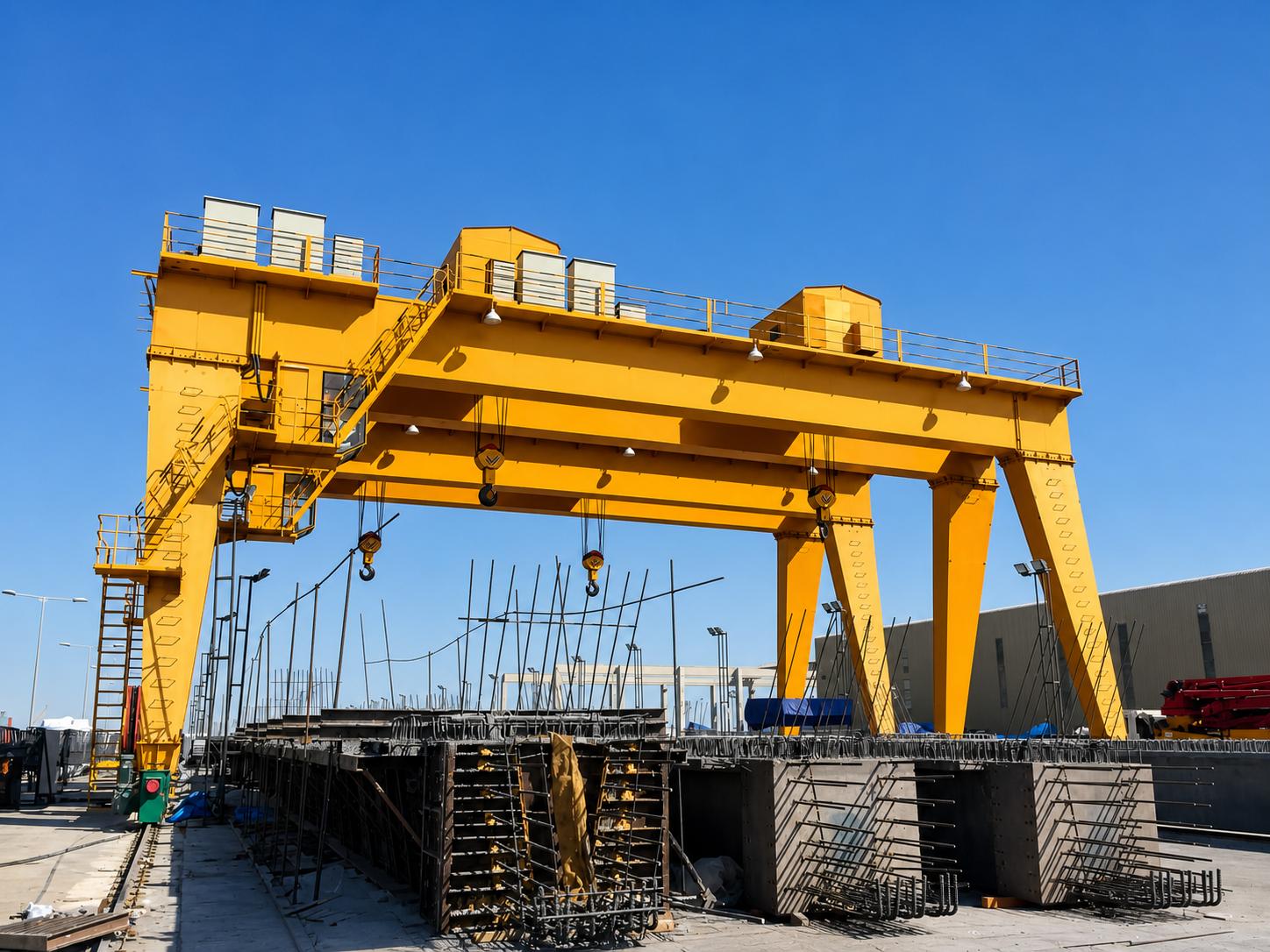
Double-girder gantry crane: It has sufficient structural rigidity, strong carrying capacity and high operating stability. It is suitable for large-tonnage and ultra-deep well heavy-duty continuous construction conditions. It is the mainstream supporting equipment for major underground infrastructure projects such as large-scale tunnels, subways, and mines.
Single winch and double winch system
Single winch system: simple structure, easy operation and maintenance, low cost, suitable for all kinds of conventional shaft lifting operations, can fully meet the basic operation needs of standardized underground construction, and is extremely versatile.
Double winch system: adopts double-rope independent drive mode, which can not only distribute heavy-duty pressure, but also realize redundant protection of operations, effectively avoid the risk of single-point failure, and is suitable for high-load and high-risk construction scenarios such as large-piece hoisting of shield machines and heavy-duty operations in ultra-deep wells. Outstanding safety and security performance.
Fixed and mobile door frames
Fixed gantry: The overall structure is stable and reliable, with strong deformation resistance, stable long-term continuous operation accuracy, no displacement deviation, high safety and reliability, and is suitable for long-term, normalized, and uninterrupted construction scenarios of single shafts. It is a standard supporting facility for fixed wellhead operations.
Mobile gantry: it supports orbital shift operations, has high flexibility, and can be adapted to working conditions such as alternating construction of multiple shafts and temporary avoidance of wellheads, and is perfectly adapted to multi-station and complex underground construction sites.
Customized configuration of restricted venues
For scenes where urban construction sites are small, there are obstacles at high altitude, and the site is restricted, exclusive solutions such as narrow-span door frames, short compact winches, foldable and disassembly door frames, and ground anchoring structures can be customized to adapt to special construction conditions.
At the same time, the inner diameter of the shaft, the well wall support structure, and the wellhead guidance system will directly affect the span of the gantry, the center distance of the rope, and the design of the load limit. The equipment structure needs to be customized according to the shaft parameters.
Safety Systems for Underground Shaft Hoisting
The risk of deep well lifting operations is extremely high. Load falling, over-rolling, rope breaking, and brake failure will all cause major safety accidents. A complete set of safety systems must be fully equipped and checked regularly.
Overload protection system
The equipment is equipped with a real-time load monitoring device and an overload limiter. When the load exceeds 110% of the rated value, a sound and light alarm is automatically triggered. Upward lifting operations are prohibited and can only be lowered and unloaded. At the same time, it avoids the overload tension caused by the stuck hopper and protects the equipment and the well structure.
Emergency braking system
Using the safety principle of power-loss braking, the brake is released when the power is normally powered on, and the spring force automatically locks the brake during power failure, failure, and emergency shutdown, which can stably lock the full load at any deep well position to eliminate the risk of slipping and falling into the bucket.The mainstream equipment is equipped with a dual redundant brake structure, and a single brake failure does not affect the overall protection effect.
Limit protection
The equipment is equipped with a dual upper and lower limit protection structure, the first-level limit realizes the slow transition of operation, and the second-level limit triggers emergency power-off braking.Double protection can effectively eliminate the problem of hopper rushing to the top and falling to the bottom, avoid high-risk hidden dangers such as wire rope release and reel release, and completely solve the failure of over-winding and over-discharging in deep well operations, and ensure the safety of the whole lifting process.
Regular inspection mechanism
Focus on investigating wire rope breakage, corrosion, deformation and wear defects, checking the loss of reel rope groove and pulley operating conditions, and regularly checking the wear thickness of brake pads and brake elasticity performance.Carry out maintenance in strict accordance with the ISO 4309 wire rope scrap standard, replace aging and worn-out parts in a timely manner, prevent the operation of equipment with diseases, and avoid mechanical failures and safety hazards from the source.
Emergency stop and interlock control
The equipment operation station and key operating areas are equipped with independent hardware-type emergency stop buttons, relying on dedicated circuit control, which can instantly cut off the power of the equipment, start the emergency braking, and quickly deal with emergencies.
At the same time, it is equipped with an intelligent interlocking protection system. When the maintenance door is opened, the limit device is abnormal, and the core components fail, the system will automatically lock the operating procedures, prohibit the operation of the equipment, and mechanically eliminate safety accidents caused by illegal operations and sick operations.
Man-machine lifting partition control
Manned operation of material buckets is strictly prohibited!The safety factor, protective structure, and braking configuration of material lifting equipment cannot meet the needs of personnel lifting.Personnel lifting must use special manned cages, equipped with independent overspeed protection, anti-fall devices, higher safety factor ropes and exclusive protective structures, and strictly follow the industry standards for personnel lifting.
Common Problems and How to Avoid Them
- Consequences of failure with insufficient lifting capacity: motor overload, brake overheating, inability to lift heavy-duty materials, shutdown and delay of construction period.Avoidance plan: Select the type according to the peak load of the project + safety margin, including the weight of the spreader and hopper, not according to the average load.
- Consequences of insufficient wire rope length failure: the late shaft cannot be bottomed out after deep excavation, and the rope and reel need to be replaced.Circumvention plan: Design the rope length according to the final construction depth, and reserve the redundant length and reel dead rope ring.
- The consequences of failure with a large swing in the load: colliding with the well wall, damaging the equipment and the structure of the well, there are safety risks.Avoidance plan: accurately calibrate the rope center, install a manhole guide device, adopt flexible acceleration and deceleration control, and prevent sudden start and stop.
- Consequences of overheating failure of brakes and winches: accelerated aging of components, brake failure, equipment failure and shutdown.Solution: Match the equipment of the continuous working system, choose the motor and brake system with excellent heat dissipation performance, and install temperature monitoring and overheating protection.
- Inconvenient maintenance and overhaul, consequences of failure: daily detection is not in place, and the accumulation of hidden dangers causes failure.Circumvention plan: Reserve the maintenance platform and operating space during the equipment design phase to ensure that the core components can be quickly tested, maintained, and replaced.
Maintenance Checklist for High-Lift Shaft Winch Systems
Standardized and normalized maintenance is the key to ensuring the long-term stable, safe and reliable operation of equipment. It can effectively avoid safety accidents caused by aging components and hidden failures, and extend the service life of equipment. The complete set of standardized maintenance processes is as follows:
- Daily inspection: Comprehensively check the appearance status of the wire rope, the regularity of the reel, the bolt fastening of the structure of the whole machine, the flexibility of the pulley rotation, and the sensitivity of the limit switch, test the no-load braking performance, and verify the integrity of the terminal carrying components such as hoppers and spreaders to ensure that the hidden dangers are cleared daily.
- Special rope inspection: Special investigations of wire ropes are carried out every week, focusing on checking defects such as broken wire, wear, corrosion, deformation, etc., accurately measuring changes in rope diameter and making ledger records, strictly evaluating working conditions against scrap standards, and timely replacement of over-standard and aging ropes.
- Brake system testing: Carry out daily practical tests of brake functions, complete static load-bearing brake verification regularly, and carefully check the degree of brake pad wear, the elastic state of the brake spring, and the flatness of the brake disc surface to ensure that the brake system is responsive and reliable. Lock.
- Maintenance of reel and pulley: Regularly check the wear and deformation of the reel rope groove, investigate abnormal problems such as pulley operation caton, abnormal noise, and high temperature, and fill the bearings with lubricating grease in time to ensure the smooth operation and controllable wear of the rope wheel transmission system.
- Motor and reducer maintenance: Normalize the operating noise, working temperature and vibration of the equipment, regularly test the insulation resistance of the motor, and replace the gear oil of the reducer on time to ensure the stable output of the power transmission system and prevent overload and abnormal noise failures.
- Electrical system inspection: Regularly investigate hidden dangers such as loose electrical circuits, moisture, and overheating, and comprehensively verify the frequency conversion speed control system, wireless control device, emergency stop button, and safety interlock function to ensure accurate electrical control and timely protection response.
- Structure and foundation inspection: Regularly check the integrity of the door frame welds and the torque of the connecting bolts to meet the standards, verify the stability of the outriggers and foundation anchoring, and accurately investigate hidden hidden dangers such as fatigue cracking and loosening of steel structures to ensure the structural stability of the whole machine.
- Regular load testing: After equipment installation, commissioning, overhaul and transformation, it must complete 125% static load and 110% dynamic load performance testing; regularly entrust third-party institutions to carry out professional testing, and keep the test ledger completely to ensure that the load performance of the equipment meets industry specifications and construction standards.
Conclusion
Tunnel and underground excavation gantry cranes, combined with high-lifting shaft winches, are important equipment for the construction of deep shafts, tunnels and underground projects.The selection should focus on matching the construction depth, peak load, continuous operation intensity and the harsh underground environment, while improving the safety protection and maintenance system to avoid the construction risks caused by low-profile or non-standard configurations.
Choosing a professional manufacturer with engineering design, custom manufacturing and after-sales capabilities can ensure that the equipment accurately matches the working conditions of the project.Henan Mine Crane can provide customized lifting solutions according to the lifting depth, load and on-site conditions of the underground project to help the project achieve safe, efficient and stable construction.