

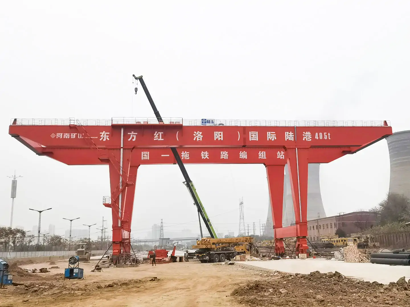
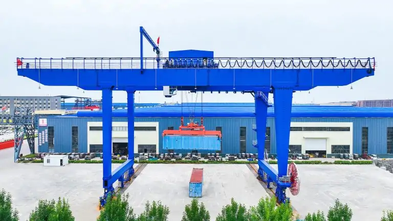

100-Ton Outdoor Gantry Crane: Wind Load, Rail Gauge, and Anti-Derailment Requirements
A single high-wind incident can overturn a fully assembled 100-ton outdoor gantry crane crushing operator cabins, deforming runway rails, and triggering costly shutdown investigations. Yet this category of equipment continues to be specified, procured, and installed without adequate attention to three engineering requirements that are directly linked to outdoor catastrophic failure: wind load calculation, rail gauge tolerances, and anti-derailment device selection.
This guide cuts through the complexity. Whether you are an engineer specifying a 100-ton rail-mounted gantry crane for a precast bridge yard, a port terminal, or a heavy-industrial storage facility, you will find a precise, standards-based breakdown of each requirement, how they interact, and what compliance looks like in practice.
What Makes a 100-Ton Outdoor Gantry Crane Different From Lighter Configurations
Before addressing wind and rail specifics, it is worth understanding why 100-ton outdoor machines occupy a distinct engineering category.
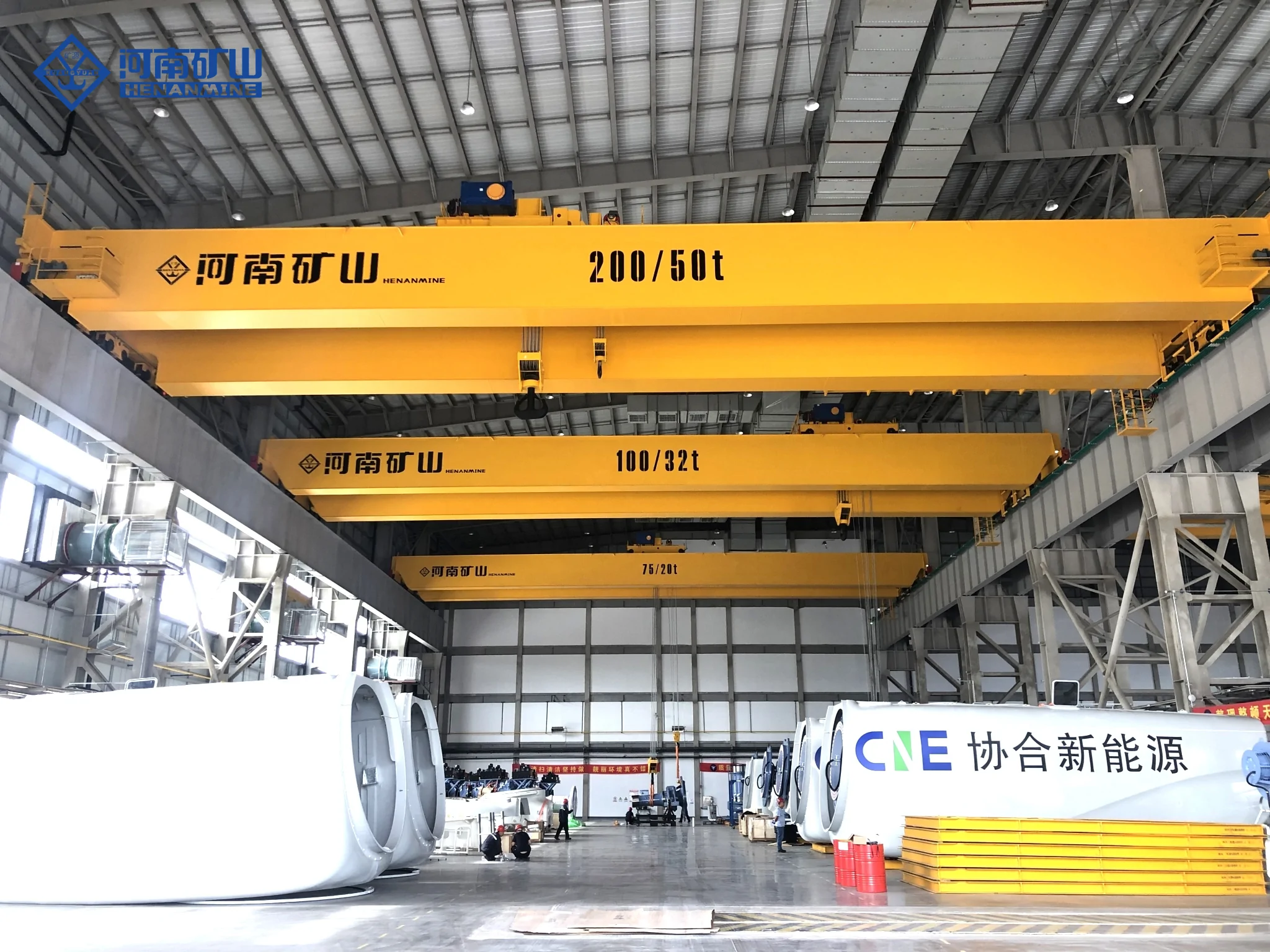
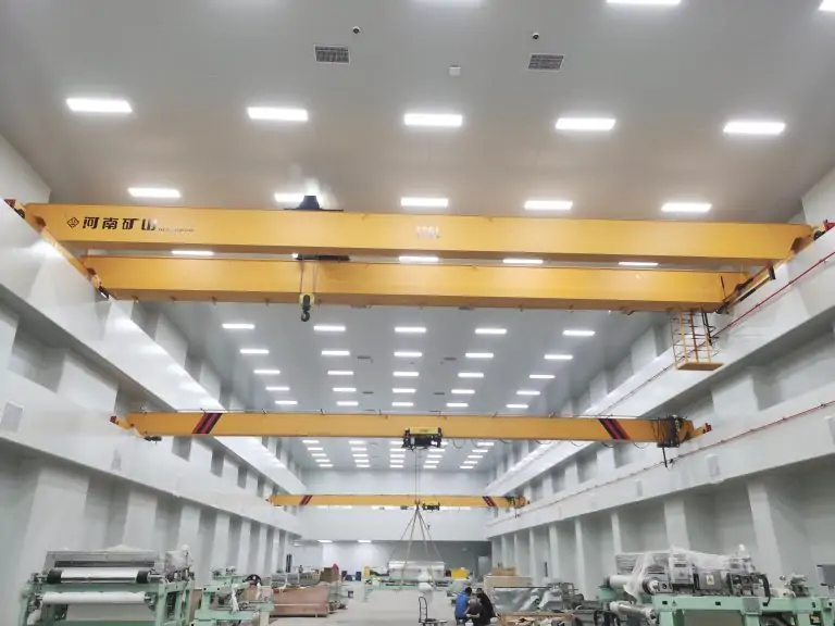
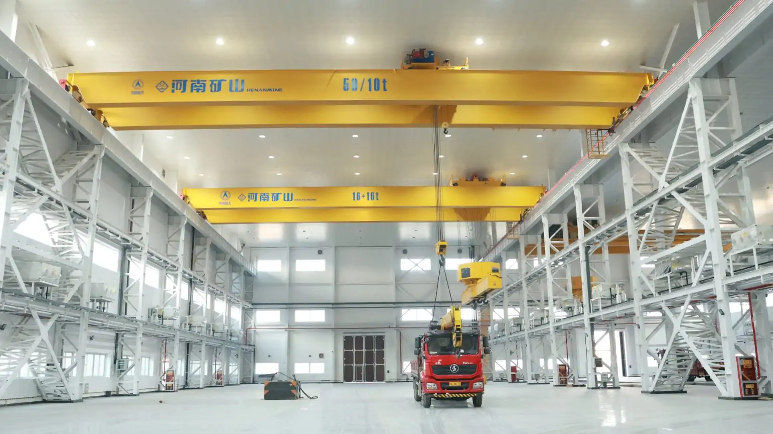
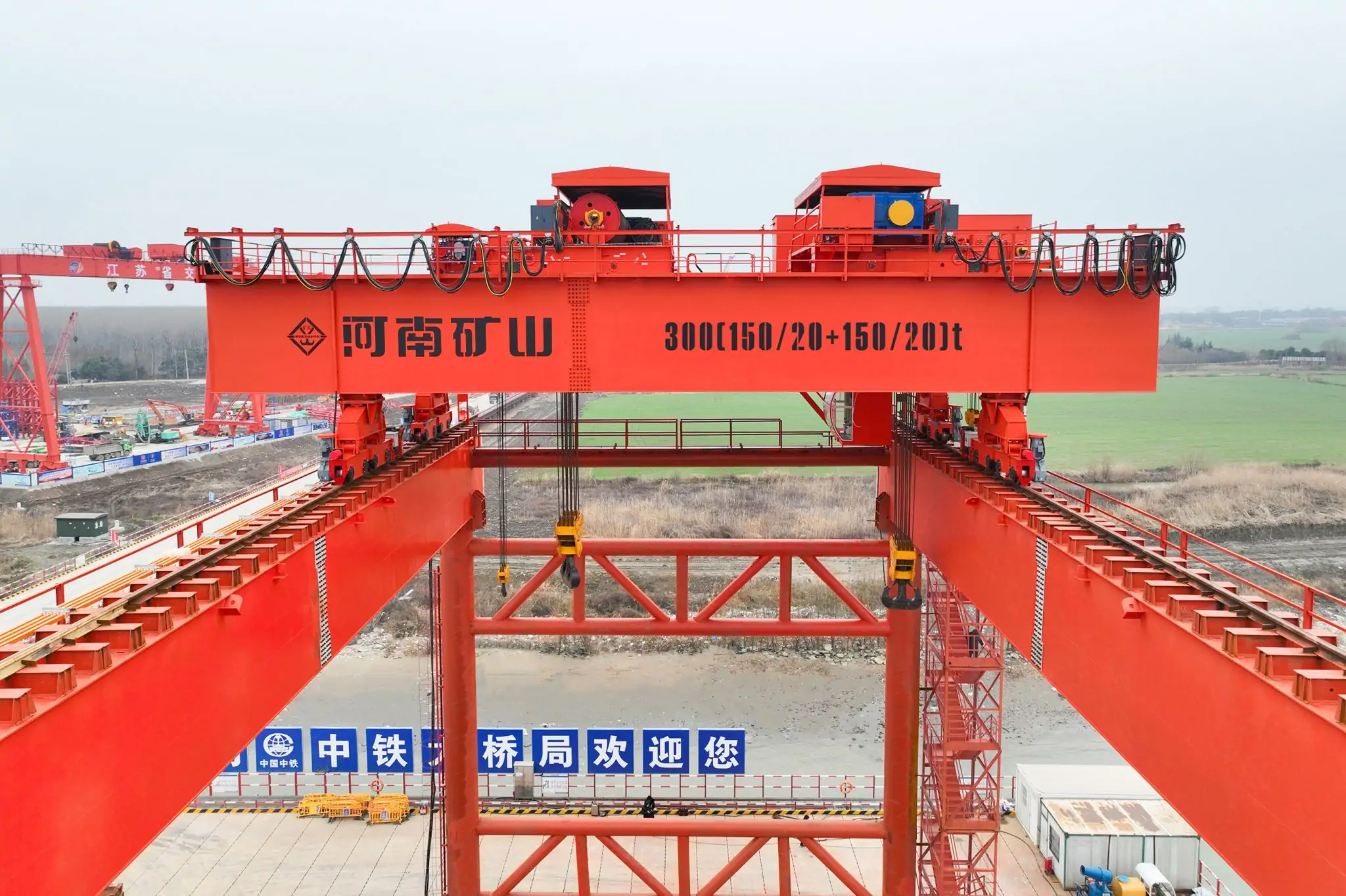
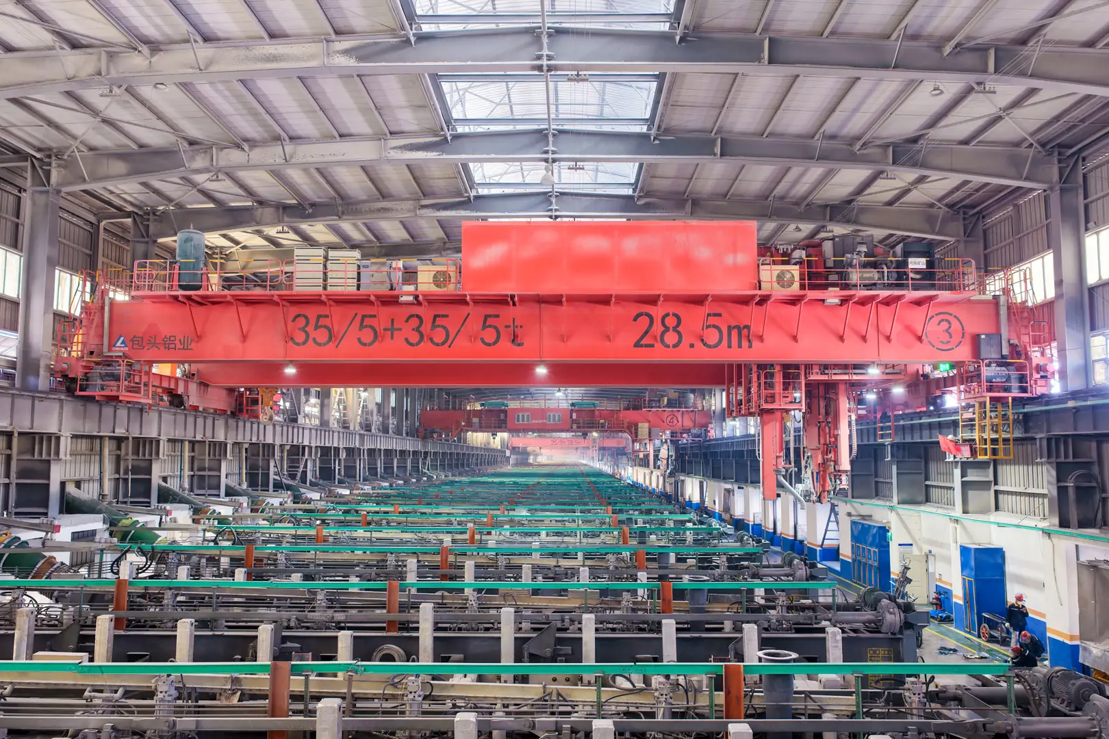
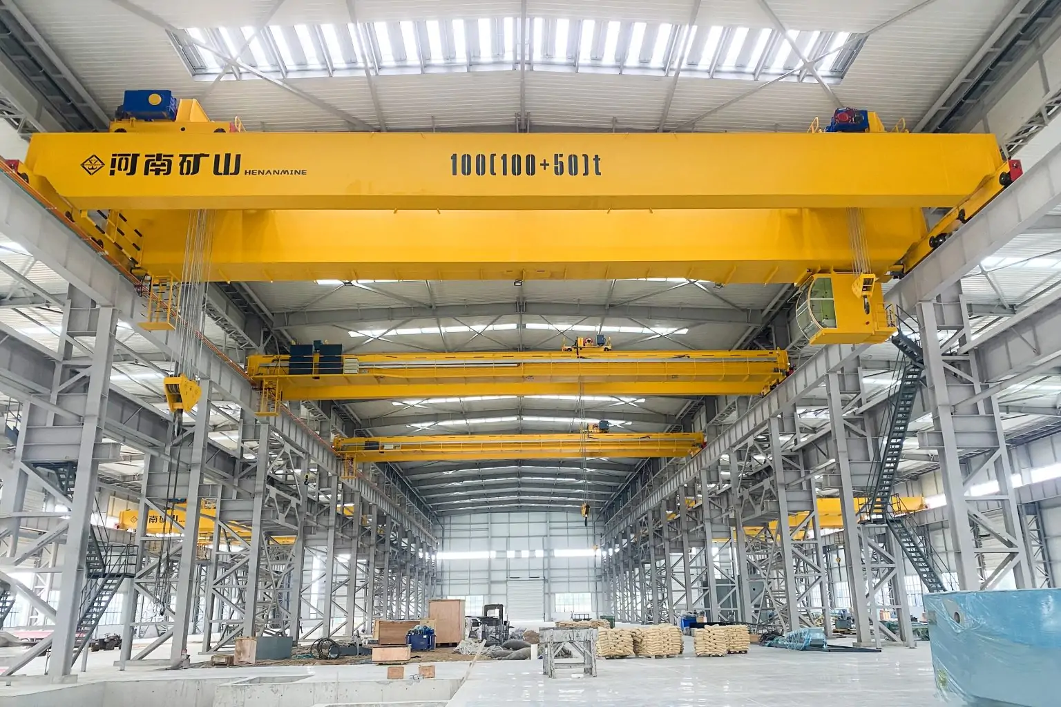
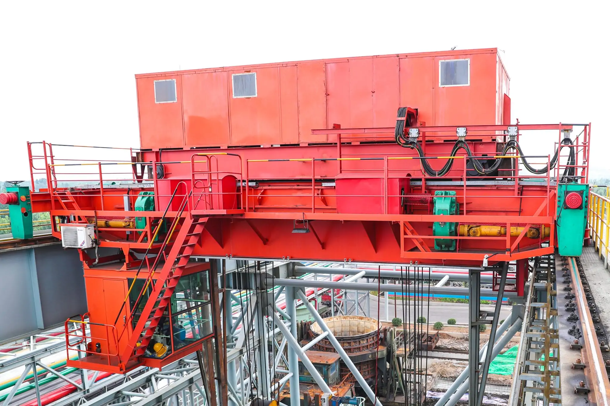
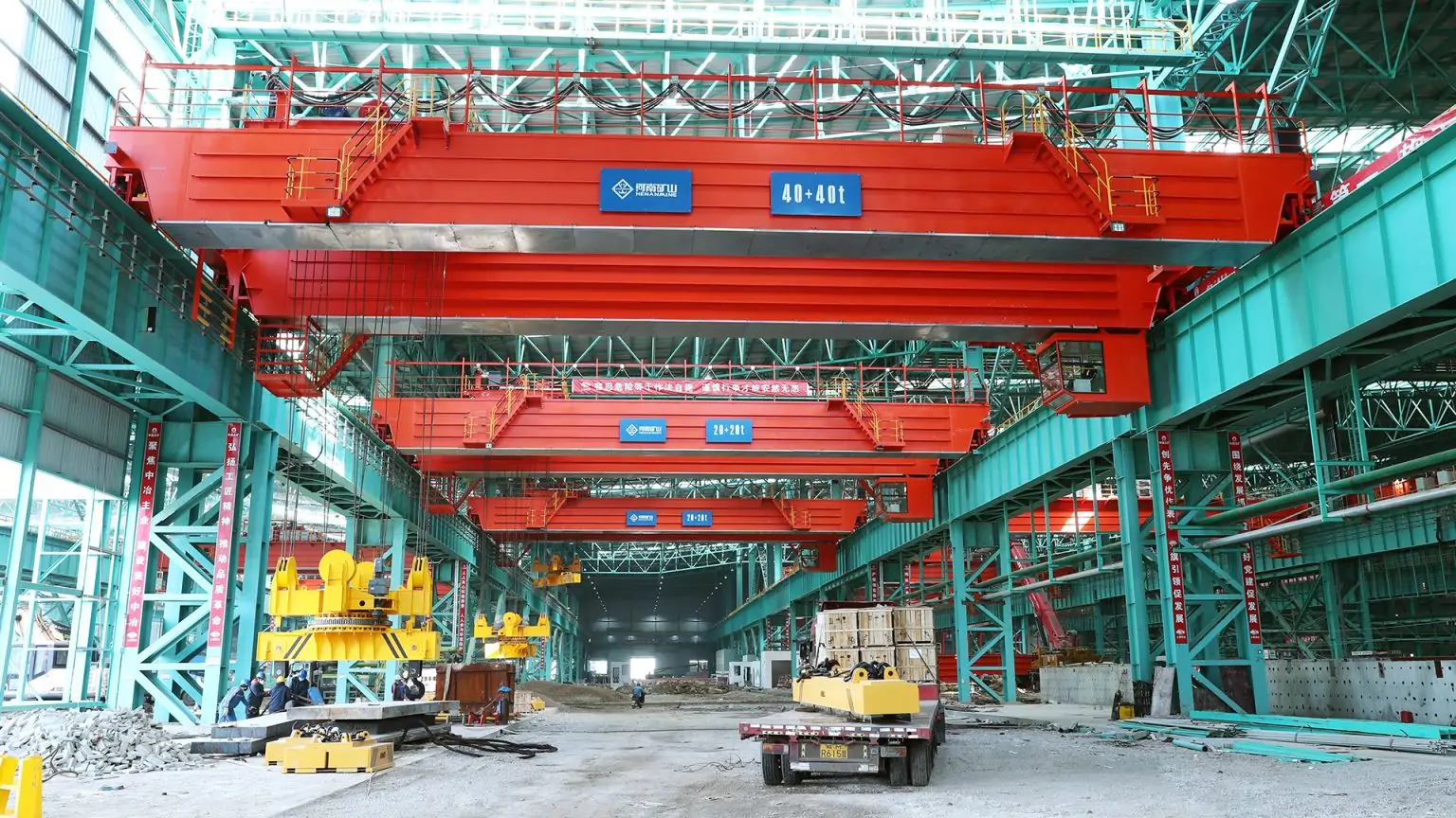
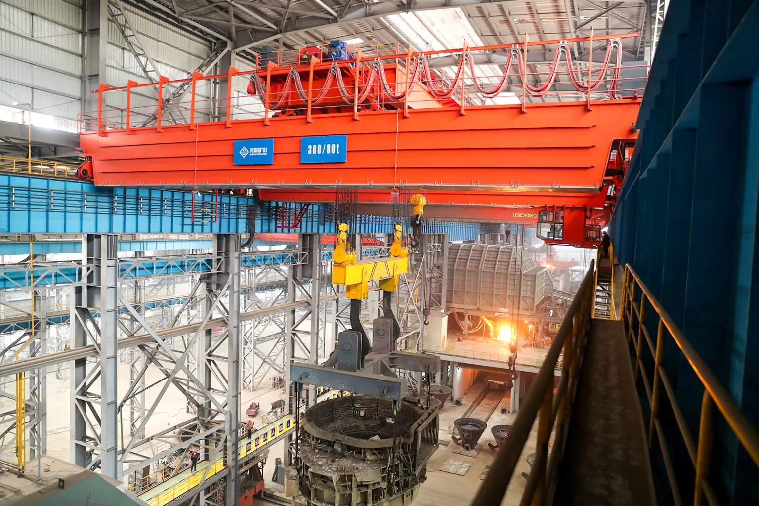
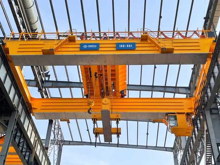
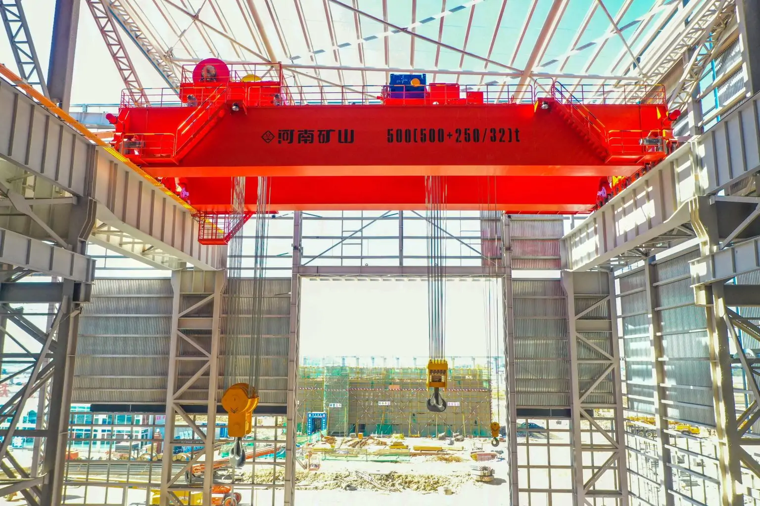
At this capacity, the crane almost always features a double main girder structure. This provides the bending stiffness and torsional resistance needed when wind forces create asymmetric lateral loads across a span that can run from 15 m to 35 m or more. Double girder designs also allow trolley systems, lifting winches, and operator cabins to be mounted with adequate clearance for safe operation at height.
The crane's large surface area main girders, end trucks, legs, and any operator house or electrical enclosures creates a substantial wind-facing profile. For a 100-ton machine with a 25 m span and 15 m lift height, the total wind-exposed frontal area can exceed 200 m². At a working wind pressure of 250 Pa (corresponding to approximately 20 m/s), that translates to a lateral wind force on the order of 50 kN on the structure alone before any suspended load is factored in.
Common applications for 100-ton outdoor gantry cranes include:
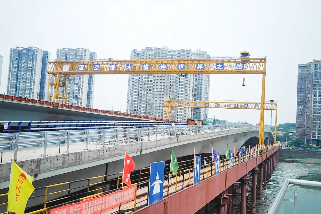
- Precast bridge and beam yards (lifting T-beams, box girders, railway precast sections)
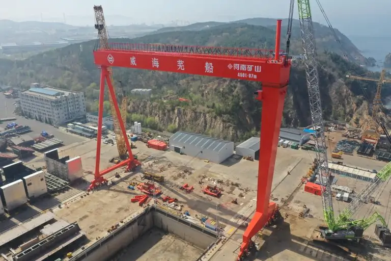
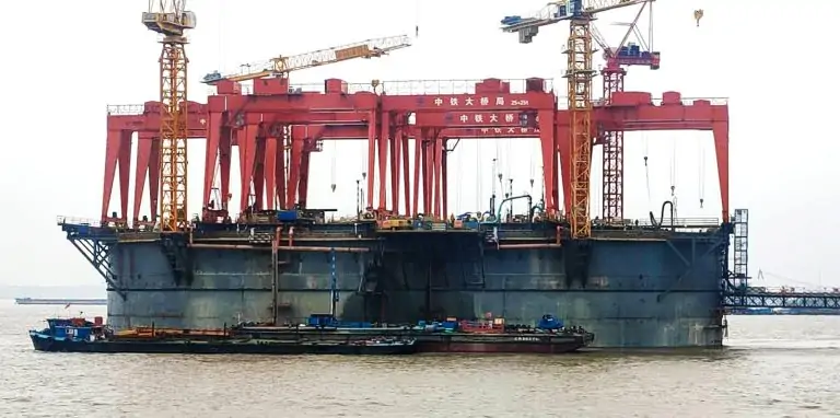
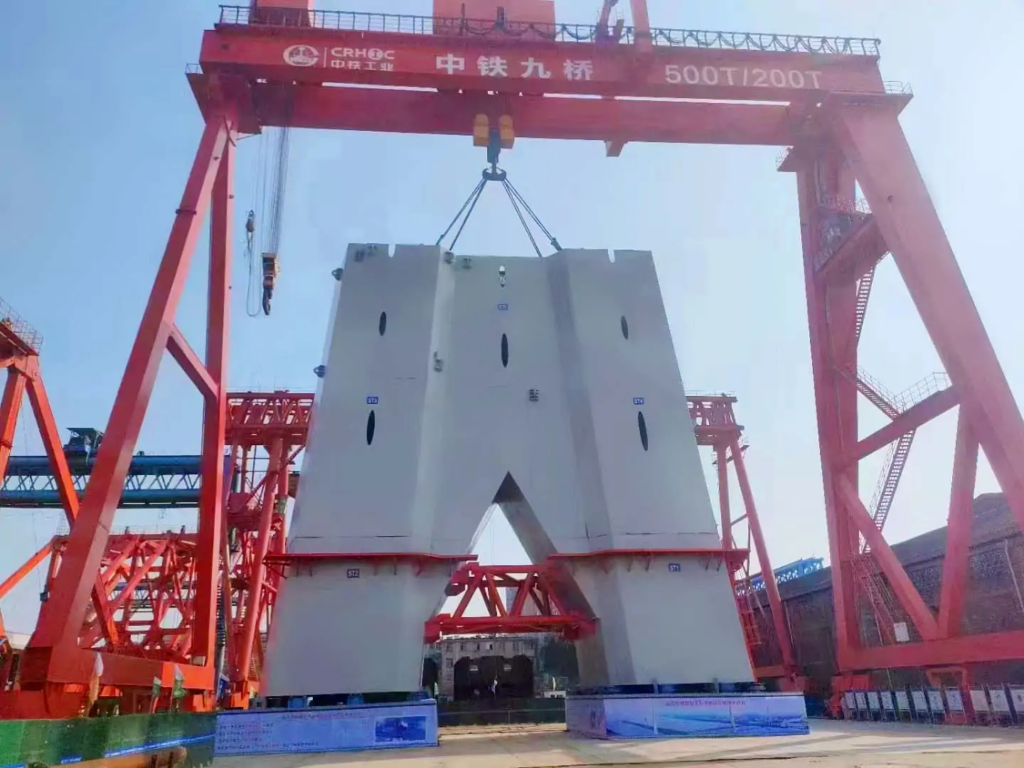
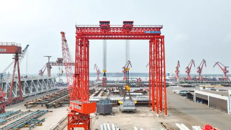
- Shipyard hull section assembly
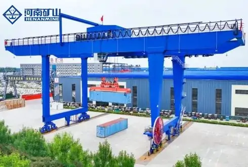
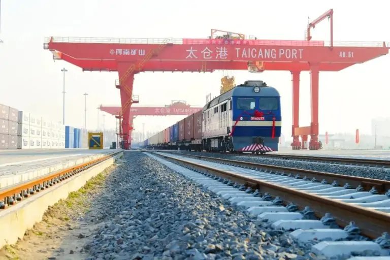
- Port bulk cargo and container handling
- Wind turbine component staging and assembly
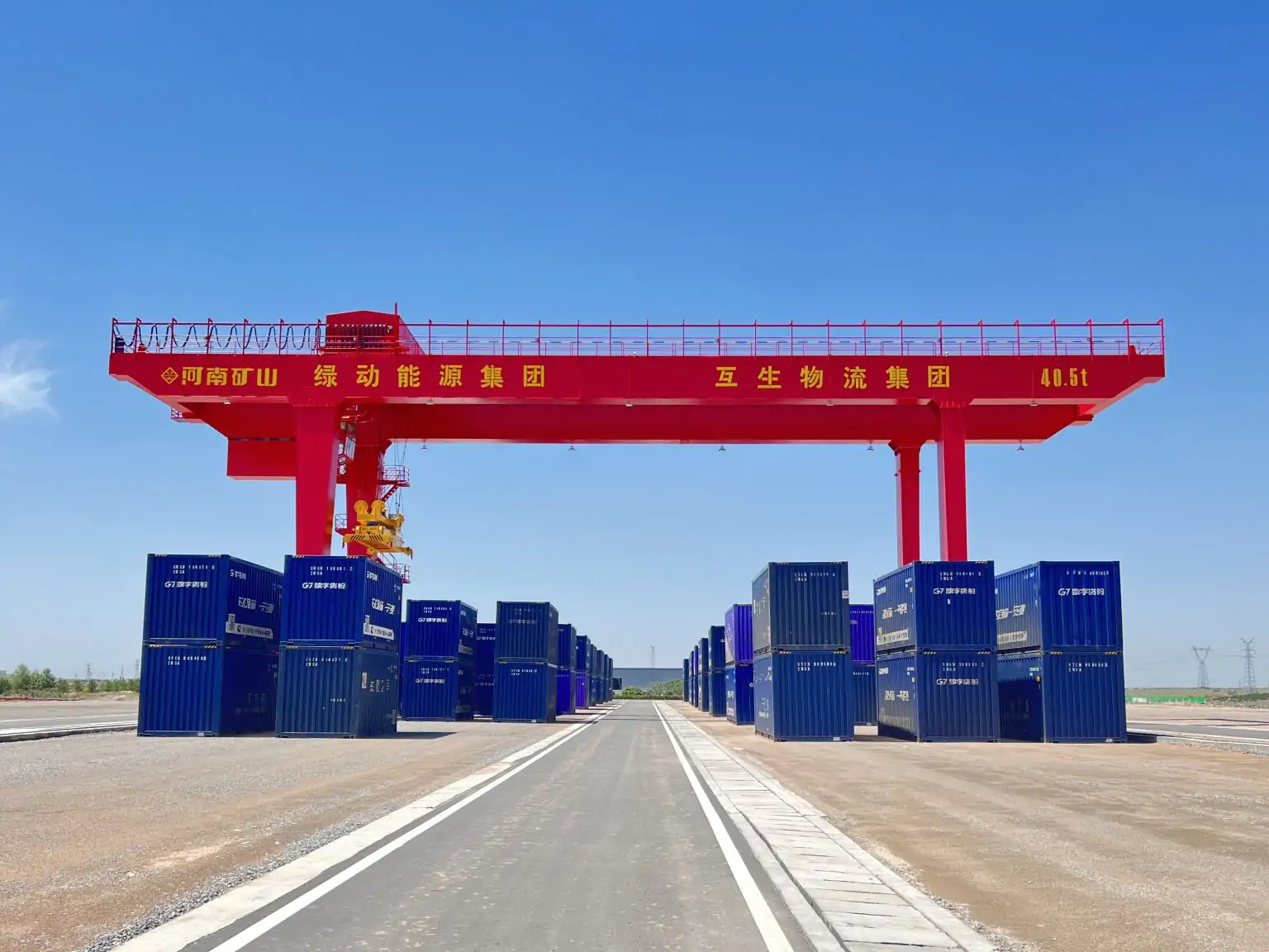
- Heavy industrial raw materials storage yards
Each application brings its own site wind exposure class, local building code obligations, and operational duty cycle all of which feed directly into the wind load and rail requirements discussed below.
Understanding Wind Load Requirements for 100-Ton Gantry Cranes
The Two-State Wind Design Framework
Gantry cranes do not experience wind in a single steady state. Engineering standards universally require design for two distinct conditions:
- Working state wind load: the maximum wind speed at which lifting operations are permitted to continue. For most outdoor gantry cranes, this threshold is20 m/s (approximately Beaufort Force 8). The structural calculation must confirm that the crane remains stable and controllable at this speed while carrying the rated 100-ton load.
- Non-working state (storm) wind load: the maximum wind speed the parked, secured crane must withstand without sliding, overturning, or structural failure. Depending on geographic location and the applicable standard, this figure ranges from 40 m/s to over 60 m/s. Port crane standards using a 50-year return period can push this threshold even higher in typhoon-prone coastal zones.
How Wind Load Is Calculated
The basic wind load acting on a crane structure is expressed as:
F = C × A × q
Where:
- F= wind force (N or kN)
- C= shape coefficient (drag factor; typically 1.2–2.0 depending on whether the structural section is solid plate, truss, or circular pipe)
- A= windward projected area of the structural element (m²)
- q= dynamic wind pressure (Pa), derived from the design wind speed for the site
For a box-girder main beam on a 100-ton crane, the shape coefficient C is typically taken as 1.3–1.4. Truss girder configurations reduce the effective wind area substantially, which is why truss designs can offer superior wind resistance though at the cost of increased fabrication complexity.
The total wind load on a complete 100-ton gantry crane must account separately for:
- Main girder(s)
- End trucks and traveling gear
- Legs and lower crossbeams
- Operator cabin and electrical enclosures
- Suspended load and hook block (in working state calculations)
North American Compliance Standards
OSHA 29 CFR 1910.179 sets binding requirements for outdoor gantry crane wind protection in U.S. workplaces. The regulation explicitly requires that rail-mounted gantry cranes located outside enclosed buildings be fitted with windproof rail clamps capable of activating automatically at preset wind speeds to prevent track instability caused by high winds. It also mandates a wind velocity indicator mounted on the crane runway structure, providing both visible and audible alarms to the operator at a predetermined threshold.
ASME B30.2-2022 the primary U.S. technical standard for overhead and gantry cranes specifies mandatory performance, inspection, and configuration requirements for wind protection devices, including interlocking rules between windproof equipment and the crane's emergency stop system.
Washington State's WAC 296-155-54200 is illustrative of how OSHA and ASME requirements translate into enforceable state code: it requires a wind velocity indicator for every outdoor overhead and gantry crane, mounted on the runway structure, giving visible and audible alarm at a predetermined wind velocity.
European and Chinese Standards
Under European FEM and EN 13001 standards, wind load classification runs from W0 to W3 based on geographic exposure. Most open outdoor installations fall in class W2 or W3. The EN framework requires that structural calculations explicitly demonstrate resistance to characteristic wind pressure for the 50-year return wind event.
China's GB/T 3811 (crane design standard) and the port-specific JT/T 90-2020 define wind load calculation methodology for Chinese installations, with the latter requiring design based on the 50-year return maximum wind speed and prescribing typhoon preparedness measures including returning to anchored positions, engaging anti-slip brakes, tensioning windproof cables, and applying rail clamps and wedges.
Rail Gauge Requirements: Sizing the Running System for 100-Ton Loads
Defining Rail Gauge in Gantry Crane Context
Rail gauge for a gantry crane refers to the center-to-center horizontal distance between the two runway rails on which the crane's end trucks travel. This measurement is distinct from but related to the crane's structural span (the distance between the centerlines of the supporting legs). For most designs, rail gauge equals span at the base rail level.
Getting rail gauge right is not optional. An undersized gauge relative to the crane's height, load, and operating wind exposure creates an inherently unstable machine that is prone to overturning and rocking under lateral loads. An oversized gauge wastes civil foundation resources and increases runway construction cost.
Typical Rail Gauge Ranges for 100-Ton Outdoor Cranes
For 100-ton rail-mounted gantry cranes, spans and corresponding rail gauges typically fall in the following ranges:
| Application | Typical Span / Rail Gauge | Notes |
| Precast beam yard | 15–25 m | Lifting height 8–15 m |
| Port bulk handling | 18–35 m | Often with cantilevered outreach |
| Shipyard assembly | 25–40 m | Stiff-leg + flex-leg beyond 30 m |
| Industrial storage | 15–20 m | Compact footprint preferred |
Design rule: For spans under 30 m, both legs are typically rigid (stiff legs). When span exceeds 30 m, one leg is designed as a flexible leg allowing thermal expansion and deflection without introducing secondary stresses into the main frame.
Rail Profile and Fastening Requirements
The rail must be matched to the wheel load imposed by a 100-ton crane. At full rated load with trolley positioned at mid-span, the maximum wheel load on a double-girder 100-ton gantry can reach 250–400 kN per wheel depending on span and configuration. This typically dictates:
- Rail section:QU70, QU80, or QU100 (Chinese standard) / CR100 or heavier (North American ASCE rail profiles)
- Fastening:Spring clamp or bolted fishplate systems providing both vertical load transfer and lateral restraint
- Gauge tolerance:Typically ±3 mm per 10 m of rail length under CMAA and FEM guidelines; tighter tolerances for high-speed or precision cranes
Rail straightness and gauge consistency over the full runway length are critical to preventing wheel flange wear and more importantly to ensuring that anti-derailment guide rollers and rail clamp systems engage correctly when deployed.
Foundation and Rail Beam Design
A 100-ton outdoor gantry transmits very high concentrated loads into the runway rail beams and their supporting foundations. Civil engineers must account for:
- Static wheel loadfrom dead weight plus rated load
- Dynamic amplification factor(typically 1.1–1.3 for gantry bridge travel)
- Lateral wind forcetransferred through the traveling gear into the rail and foundation
- Braking forcesfrom traveling mechanism deceleration
- Settlement differentialbetween the two runway foundations, which can create gauge variation over time
Regular rail surveying gauge measurement, rail head wear inspection, and fastener torque checks is part of the required maintenance program under both ASME B30.2 and OSHA 1910.179.
Anti-Derailment Requirements: Devices, Types, and Compliance
Why Derailment Is the Primary Outdoor Wind Risk
Every documented case of an outdoor gantry crane being overturned by wind involved a sliding phase before the structure tipped. Wind forces generate a lateral load on the crane's traveling gear that, if it overcomes wheel-rail friction, causes the crane to drift along the rails. Once the crane reaches a buffer stop or encounters a misaligned rail section, derailment and potentially overturning follows.
This is why anti-derailment and anti-sliding devices are not accessories. They are primary structural safety systems.
The Three Device Categories
Rail Clamps (Track Clamps)
Rail clamps grip the sides of the rail head, preventing the crane from sliding longitudinally. They are the most widely used and most critically important wind protection device for outdoor gantry cranes. Three types are in common use:
- Manual caliper rail clamp: Operator-actuated via screw mechanism. Low cost, suitable for small cranes or as a secondary device. Requires operator action and is inadequate as the sole protection for a 100-ton machine.
- Electric rail clamp:Motor-actuated, typically integrated with the crane's wind alarm system so that when wind speed exceeds the threshold, the clamp activates automatically. Suitable for medium-tonnage outdoor cranes.
- Electro-hydraulic (spring-set) rail clamp:The preferred solution for 100-ton and larger outdoor gantry cranes. These clamps are spring-applied and hydraulically released: they engage automatically on power failure (fail-safe), and provide the highest clamping force. They are the standard specification for port cranes in typhoon-prone areas.
Rail clamps should be mounted on the crane's end truck chassis, positioned to engage the rail head with equal force from both sides. OSHA requires that windproof rail clamps on outdoor gantry cranes activate automatically at preset wind velocities manual-only systems do not satisfy this requirement for large cranes.
Anchor Devices
Anchor devices secure the crane to fixed ground points along the runway, preventing movement under storm-level winds that exceed the capacity of rail clamps alone. A typical anchor system for a 100-ton outdoor gantry consists of:
- Ground-embedded anchor bolts or sockets installed at fixed intervals (commonly every 10–20 m) along the runway
- Mating latches or pin connectors on the crane's lower cross-beam or leg base
- A storm parking position where all four anchor points can be simultaneously engaged
The non-working state design requirement that anchor devices alone must be able to bear the full storm wind load is a key engineering constraint. Where anchor devices are absent, the anti-wind braking system must be capable of independently resisting the full non-working wind load, which typically requires oversized hydraulic clamping systems.
Iron Shoes and Wedge Devices
Iron wedges (also called iron shoes) are inserted between the wheel flange and the rail to provide a mechanical block against rolling under storm conditions. They are typically used as a tertiary or backup device, deployed manually by ground personnel before an approaching storm, in conjunction with rail clamps and anchors.
Some cranes incorporate track-pressing devices positively engaging plates that press down onto the top of the rail rather than gripping the sides which are less sensitive to rail lateral-surface condition and are common in environments where rail flanges may be contaminated by material buildup.
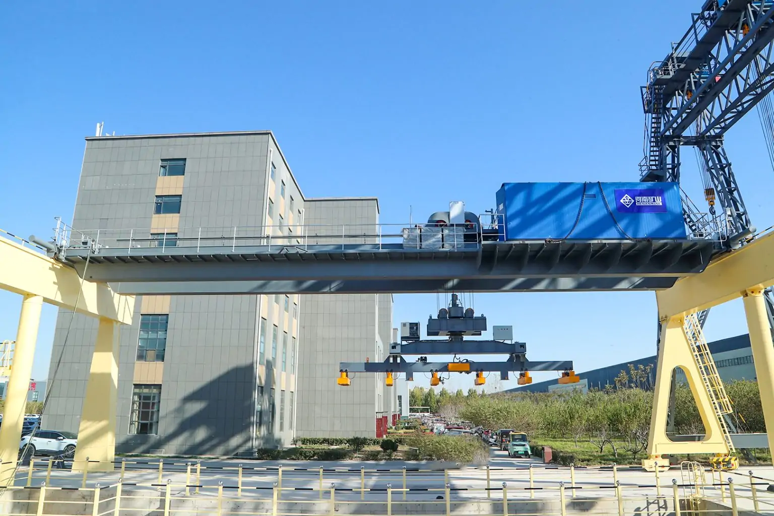
Anti-Derailment Guide Rollers
Separate from wind-protection clamps, all outdoor rail-mounted gantry cranes should be equipped with horizontal guide rollers that prevent the traveling wheels from climbing the rail head under lateral force. These rollers are mounted on the end truck and maintain a nominal clearance of 5–10 mm from the rail side face in normal operation. When a lateral force (from wind, off-center loading, or rail misalignment) pushes the crane sideways, the guide rollers engage the rail and prevent wheel climb.
Crane end trucks with sweeps devices that extend below the top of the rail in front of the truck wheels are also required under ASME B30.2 to clear debris from the rail path that could cause derailment.
Anemometer and Wind Speed Alarm Requirements
No anti-derailment system functions correctly if the operator cannot be warned in time. Outdoor 100-ton gantry crane installations must include:
- A calibrated anemometermounted on the crane runway structure at crane-top elevation (not ground level, where wind speed is systematically underestimated)
- Bothvisible and audible alarm triggered at the pre-set working wind speed threshold
- Alarm signals that are discernible from the operator's cab under operating noise conditions
- A defined operational protocol: at working wind alarm, suspend load handling; at storm wind threshold, engage all rail clamps, park at anchor position, engage anchor devices, and evacuate
Common Failure Modes and How Requirements Address Them
Inadequate Rail Clamp Clamping Force
A frequently observed deficiency in accident investigations is that rail clamps were installed but generated insufficient gripping force either because the clamp model was undersized for the crane weight, or because maintenance was inadequate and the clamping mechanism had corroded or worn. The engineering rule: the total combined clamping force of all rail clamps must exceed the calculated non-working wind force with an appropriate safety factor, typically 1.5 or higher.
Gauge Drift Over Time
Outdoor runways are subject to foundation settlement, frost heave, and thermal cycling. Gauge drift of even 10–15 mm can cause guide rollers to jam or fail to engage correctly. A formal rail inspection and gauge survey program,at minimum annually, more frequently in severe climates is part of compliance under OSHA 1910.179 and ASME B30.2 maintenance provisions.
Operator Failure to Engage Devices
Multiple incidents have occurred where storm rail clamps and anchor devices were installed but not engaged before a high-wind event. This is a procedural failure, but one that engineering controls can mitigate: automatic activation of electro-hydraulic clamps on wind alarm removes dependence on operator action during a potentially chaotic weather emergency.
What to Specify When Buying a 100-Ton Outdoor Gantry Crane
Use this checklist to ensure wind load, rail gauge, and anti-derailment requirements are properly addressed in your crane specification and supplier technical documents:
- Wind load design basis:Confirm working wind speed (m/s) and non-working storm wind speed (m/s) specified, with design standard cited (ASME, FEM, GB/T, or EN)
- Wind load calculation report: Request supplier's structural calculation showing working and non-working wind loads by component, with safety factors
- Rail clamp type and clamping force: Specify electro-hydraulic spring-set clamps for 100-ton outdoor installations; require clamping force documentation
- Automatic wind alarm interlock:Confirm rail clamp activation is interlocked with crane wind speed alarm (required by OSHA for outdoor cranes)
- Anchor device quantity and capacity:Confirm four-point anchoring at storm parking position, with each anchor device rated for its share of non-working wind load
- Rail gauge and tolerance:Confirm rail gauge matches site civil design; request gauge tolerance specification and acceptance criteria
- Rail section specification:Confirm rail profile (QU80, QU100, CR100, or equivalent) matched to maximum wheel load at rated capacity
- Anemometer specification:Confirm anemometer type, alarm setpoints, and alarm modalities (visible + audible)
- Guide roller clearance:Confirm horizontal guide roller or anti-derailment roller clearance specification (5–10 mm from rail face)
- Buffer and end stop design:Confirm travel limit switches, buffers, and rail end stops are rated to prevent derailment at maximum travel speed
- Applicable standards compliance:Request written confirmation of compliance with OSHA 29 CFR 1910.179 and ASME B30.2-2022 (or applicable local equivalents)
- Maintenance documentation:Confirm operation and maintenance manual includes rail gauge inspection intervals, clamp inspection procedure, and storm procedure
Conclusion
A 100-ton outdoor gantry crane is an asset that can deliver decades of reliable heavy-lift service or become a liability in the first major storm if wind load engineering, rail gauge precision, and anti-derailment systems are not treated as core design elements rather than afterthoughts.
The framework is clear: design structurally for both working and non-working wind states, match rail gauge and rail profile to the actual wheel loads your machine generates, specify electro-hydraulic spring-set rail clamps with automatic wind alarm interlock, install anchor devices at storm parking positions, and establish a maintenance program that keeps all of these systems in measurable, documented compliance with OSHA 1910.179 and ASME B30.2-2022.
Procurement teams should demand wind load calculation reports, clamp force documentation, and standard compliance statements as part of the technical package not as an optional supplement. A supplier that cannot produce these documents is not a supplier whose crane you want operating in an open yard at maximum capacity.
Henan Mine Crane boasts a professional team and extensive experience, with engineers well-versed in site-specific wind conditions and applicable standards. We dedicate ourselves to rigorous preliminary engineering design to precisely meet our customers' needs.