
How to Evaluate Existing Runway Beams Before Installing an Overhead Crane
When replacing the bridge crane, whether the original track beam can continue to be used cannot be judged only by the rated tonnage of the old equipment.The real evaluation object is runway beams (crane track beams) and their load-bearing systems composed of tracks, connections, support columns and foundations: whether they can still withstand the actual wheel pressure, operating effects and future repetitive loads of new equipment under the existing state of damage.
Reliable conclusions come from original data verification, on-site inspection, structural verification and installation geometry retest.This article mainly discusses the upper bearing system of the wheel running on the top track of the beam; the lower bearing system also involves different issues such as local bending of the lower flange.The decision on reuse, reinforcement or replacement shall be made by the structural engineer in charge of the project based on clear equipment parameters and conditions of use.
Review the Original Design Specifications and Structural Documentation
Collect Existing Runway Beam Drawings
The original structure diagram, calculation book, material certificate and completion record can explain the beam cross-section, steel grade, weld and bolt configuration, and the crane load originally used.The longitudinal support span, column spacing and transverse span between the two tracks of the track beam must be recorded separately, and the two cannot be mixed.The support form, lateral support, and the original design work level also affect the calculation.
Drawings can only provide a starting point, and on-site physical objects are the basis for the status quo assessment.When the data is missing, supplementary information can be obtained through dimensional surveying and mapping, thickness testing, and necessary material testing; when the steel performance cannot be confirmed, common grades cannot be directly applied, especially for subsequent welding reinforcement to retain weldability verification.
Compare the Original Design with the New Crane Requirements
When comparing old and new equipment, in addition to the rated lifting weight, it is necessary to check the weight of the bridge, the lifting mechanism and the weight of the trolley, the number of wheels, the wheel track, the maximum and minimum wheel pressure, and the limit position of the trolley.Two cranes with the same 10 t may have different bending moments and bearing reaction forces on runway beams due to different weights and wheel arrangements.
The level of work and the actual frequency of use must also be compared.Equipment originally used for occasional maintenance, even if the tonnage remains the same, may significantly increase the load cycle after being changed to continuous production; the working level identification of the new equipment cannot automatically prove that the old support structure has the same fatigue adaptability.
Identify Previous Modifications or Structural Reinforcements
The new reinforcement plates, openings, incisions, brackets and welding accessories added on the site should correspond to the records of previous retrofits.They may change the cross-section, load transfer, or stress concentration position.Once reinforced does not mean that it is still qualified, especially if there is no change in the calculation book, welding record or acceptance information, it needs to be re-incorporated into the structural model.
Inspect the Physical Condition of Existing Runway Beams
Check for Cracks, Corrosion, and Material Deterioration
The inspection should cover the flange, web, stiffener end, weld and connection vicinity, and focus on recording the location, scope and severity of the defect.Humid stagnant water, chemical media and high temperature-affected areas should be checked in combination with exposure history.The appearance of corrosion cannot directly represent the loss of bearing capacity. The calculation needs to use a representative remaining thickness and identify local pitting or severe thinning.
Visual inspection cannot rule out small cracks.Magnetic powder detection is suitable for surface and near-surface defects of ferromagnetic steel, and penetration detection is for surface opening defects; internal defects can be selected according to the structure and detection conditions. Ultrasound and other methods.The scope, method and judgment criteria of testing should be formulated by professionals. When suspected load-bearing cracks are found, the relevant operations should be isolated and the risks assessed.
The inspection record should also indicate the reachable range, the state of surface treatment, and the location where it failed to be inspected.The covered welds or areas obscured by rust accumulation cannot be directly marked as defect-free; when these locations may control load-bearing or fatigue conclusions, targeted supplementary inspections should be arranged so that the state of the components used in the calculation is supported by actual evidence.
Examine Beam Deformation and Structural Damage
The bending, torsion, wave deformation of the wing edge and local buckling of the web of the beam need to be described by measurement rather than visual inspection.The evaluation should also distinguish between the design pre-arch, the elastic deformation under the current load, and the permanent deformation after unloading.The latter may involve past overloading, collision, or support changes, and cannot be determined to have been resolved by adjusting the position of the rail.
Inspect Connections, Bolts, and Welds
The connection inspection includes beam and column nodes, supports, lateral knots and related column foot components.Missing or loose bolts, deformation of the hole wall, cracking of the weld and emptying of the bottom plate may all change the original force transmission method.For runway beams, repeated loosening may also be related to vibration or abnormal constraints. Simple fastening cannot replace cause analysis.
The current connection must also review the strength and applicable anti-slip requirements according to the new load.Before welding or replacing bolts, the original functions, materials and construction conditions of the connection should be confirmed first, so as to avoid restricting the normal rotation of the beam end during the repair process, or forming new fatigue-sensitive details.
Verify the Load-Bearing Capacity of Existing Runway Beams
Calculate the Total Crane Loading
The load model must first clarify the weight of the bridge, the lifting mechanism and the weight of the trolley, as well as the definition of the rated lifting weight in the equipment data; additional weights such as spreaders must also be clearly included in the location to prevent omissions or duplication.The wheel pressure gauge provided by the manufacturer should indicate the unit, load status, trolley position, and whether it already includes power influence or design coefficient.
Dividing the total weight by the number of wheels can only get the average value, and cannot replace the design wheel pressure.When the trolley approaches one side of the track, the reaction forces on both sides will change; the distribution of the wheels on the same side is also affected by the end beam structure, equalization device and wheel track.The maximum wheel pressure is used to identify high-load operating conditions, while the minimum wheel pressure is related to the wheel-rail contact, the amplitude of load change and the relevant horizontal force combination.
For example, assuming that the rated lifting weight of the old and new equipment is the same, the bridge of the new equipment is heavier, and the trolley can be closer to one side of the track, even if the span of the plant remains the same, the load on the near-side track beam may also increase.If the wheel track changes at the same time, the arrangement of the most unfavorable wheels on the same beam will also change.This is a hypothetical scenario that explains the comparison method and does not represent a fixed increase in a certain model.
The lifting power effect, the start braking of the cart and the trolley, the operation skew and the applicable buffer effect need to be handled according to the corresponding working conditions.The direction, height of action, and transmission position of the transverse and longitudinal forces must be clear; when using the side guide wheel, it is also necessary to verify whether the horizontal force is concentrated on one side of the track.When there are multiple cranes, outdoor wind loads, or other related effects, they should be combined according to the design basis to avoid simply superimposing all peaks.
In addition, the weight of the track beam, steel rail and fixed accessories belongs to the load of the support structure itself, and cannot be missed because the weight of the bridge frame has been listed in the equipment wheel pressure gauge.If the new maintenance platform or suspension facility is added, the model should also be entered according to the actual connection location.The load list should indicate who provides each weight and which component is passed to, and distinguish between long-term fixed action and mobile wheel pressure.
Evaluate Beam Bending, Shear, and Stress
The structural verification should allow the wheel load group to move along the beam, looking for the bending moment, shear force and bearing reaction envelope of each cross-section.The maximum bending moment and maximum shear force are usually not controlled by the same wheel position, and the crane cannot only be calculated when it is parked in the span.The model should also adopt on-site confirmed support and lateral constraints, and the failed pull knot cannot continue to be regarded as an effective support.
The check of runway beams includes not only the overall bending and shear, but also the local pressure near the wheel pressure, the local buckling of the web, and the related flange stress.The track deviates from the center of the web, or the horizontal force acts on the top of the track, which may introduce additional torsion and lateral bending; only the vertical bending moment divided by the cross-section modulus cannot cover these effects.
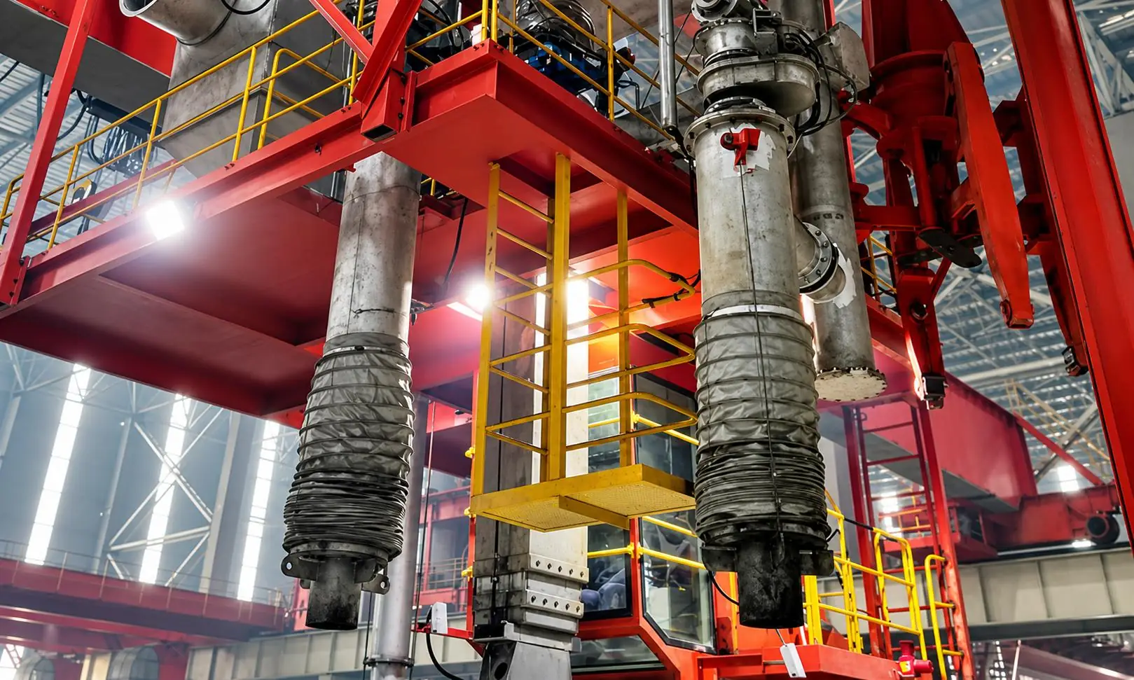
Lateral torsional buckling depends on the constraints of the compressed flange, the unsupported length and the load conditions, while the partial buckling of the cross-section is related to the size of the plate and the remaining thickness.Whether the track can be included in the stiffness or strength of the beam, there must also be a corresponding connection and design basis.The effective cross-section, connection capacity and load combination specified in the specification after corrosion should be entered into the verification together.
Check Beam Deflection and Vibration
Qualified strength does not mean that the operating performance is qualified.Excessive vertical deflection, uncoordinated deformation on both sides, or excessive horizontal displacement may affect the wheel-rail contact and operating geometry.The evaluation should check the displacement of the beam itself, and also consider the overall changes caused by column side movement, bearing deformation, and foundation settlement, and distinguish these changes from the initial installation deviation.
The deflection limit must be used in conjunction with the corresponding load conditions.The coefficient load used for strength verification cannot directly replace the normal use verification load; whether it is included in the dynamic impact shall be determined in accordance with the specific provisions and equipment requirements.When there is continuous vibration or abnormal shock, the source of excitation can be analyzed in combination with the measured response, and the dynamic evaluation can be carried out if necessary. The static deflection alone cannot be used to eliminate the problem.
Assess Fatigue Resistance and Remaining Service Life
Fatigue assessment focuses on the stress range and number of cycles caused by repeated loads, not just whether the highest stress reaches the yield strength of the steel.The ends of the welds, accessory connections, stiffener joints, and cross-section mutations need to be evaluated according to specific structural details.The same maximum lifting weight, under different trolley position distribution and round-trip frequency, will produce different fatigue load histories.
Historical data should try to restore the distribution of load weight, the number of crane passes, work shifts and maintenance events as much as possible, and connect with the planned use in the future.A lifting of the equipment does not necessarily correspond to a stress cycle for each structural detail; the wheels pass by in turn, the crane goes back and forth, and the actual operating range will affect the count.
The remaining life of runway beams cannot be calculated simply by subtracting the design life from the service life.When the information is insufficient, the uncertainty can be reduced through monitoring, reasonable conservative assumptions and sensitivity analysis, but the applicable conditions should be retained for the conclusion.Cracked components also involve crack disposal and special evaluation; a non-destructive inspection has not found defects, nor can it prove that there has been no accumulated fatigue damage in the past.
Evaluate Runway Rail Alignment and Installation Geometry
Check Rail Straightness and Elevation
Track re-measurement should adopt a unified reference, record the straightness along the line, the elevation of the top of the track and the height difference between the two tracks on the same section, and indicate the temperature and loading status at the same time.Local track cushion problems, beam deformation, and column foundation settlement may show similar elevation abnormalities, so the geometric report should be able to be traced back to the corresponding support position to help identify the root cause.
Verify Rail Gauge and Parallelism
The gauge should be measured along the entire operating interval, and the dimensions of both ends cannot be confirmed only.Even if the respective straightness deviations of the two tracks meet the requirements, the combined gauge may still exceed the limit.It is also necessary to pay attention to whether the deviation change is abrupt, because the continuous correction of the wheel and the contact of the rim may exacerbate the lateral action and wear, forming a process of mutual strengthening of structural and operational problems.
The geometric deviation limit and the load deflection limit solve different problems and cannot be replaced by each other.The re-test report should indicate the tolerances used, the measurement conditions and the manufacturer's interface requirements; if the installation tolerance is for the state of the crane that is not installed, it cannot be directly judged by the on-board measurement results.The long service time of the old track cannot automatically be a reason to relax the operating geometry requirements.
Inspect Rail Fasteners and Supporting Surfaces
Rail presses, bolts, track pads, pads, joints and related welding accessories should be checked for integrity and function at the same time.The support at the bottom of the rail is not continuous, the cushion is damaged or the fasteners fail, which will change the local force transmission.When replacing the rail type or wheel configuration, it is also necessary to verify the matching of the rail head with the wheel tread, the adaptability of the fasteners, and the position of the track center relative to the beam web.
Confirm Compatibility with the New Overhead Crane
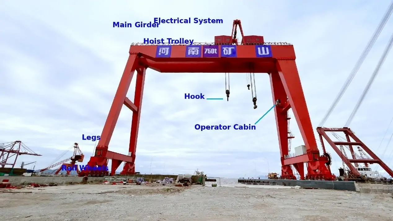
The equipment interface check includes the crane span, the same side wheel track, the end beam arrangement, the effective operating distance, the limit position of the hook, the lifting height and the end clearance.The support span of the track beam and the span of the crane across the two rails should be marked separately.The available headroom is also affected by roof frames, pipelines, sliding contact lines, maintenance facilities and operating deformation. The appropriate plane size does not mean that the complete installation conditions have been met.
Assess Supporting Columns, Brackets, and Foundation Conditions
Inspect Runway Supporting Columns
The support column should check the cross-section size, material, corrosion, verticality, local buckling and existing deformation.After the crane load is passed into the column, the axial force and the bending moment often form a combination, and the horizontal force will also cause the frame to move sideways.The stability verification of the column should be based on the real support conditions, and the second-order effect should be considered if necessary. The new vertical reaction force cannot only be compared with the axial pressure bearing capacity of the column.
Evaluate Brackets and Connection Details
The legs and brackets pass the reaction force at the end of the beam to the column, and the eccentricity of the reaction force line will produce additional bending moments in the connection area.The local carrying capacity of leg welds, bolts, stiffeners, and column flanks and webs may precede the beam control design.After runway beams are reinforced, the nodes and support components must also be reinforced, otherwise the weak bearing position may be transferred.
The lateral pull should also take into account the transmission of horizontal force and the allowable expected displacement.If the rotation of the beam end or temperature deformation is unexpectedly limited, the connection may be repeatedly forced.When repeated cracks are found in the same location during maintenance, the analysis should be expanded to the overall restraint relationship, not just the repair of visible cracks.
Review Foundation and Building Structural Conditions
The foundation assessment includes settlement history, cracks, column feet, anchors and related foundation information.Horizontal action needs to continue to pass into the foundation along the frame, support, and column feet; existing roofing, equipment, and other building loads should also be included in the applicable combination.If the new load significantly changes the reaction force of the foundation, or the settlement is still developing, further foundation and foundation verification is required, and rail adjustment cannot be regarded as the final treatment.
Check Applicable Standards and Safety Requirements
The specifications adopted by the project depend on the location, approval requirements, contract and original design basis.U.S. projects may involve ANSI/AISC 360, applicable building load specifications, and CMAA 70 or CMAA 74; the European specification system usually involves the crane function of EN 1991-3, the crane support structure of EN 1993-6, and the fatigue requirements of EN 1993-1-9, combined with the applicable national appendix.
The crane design documents of CMAA and FEM help define equipment performance and related interface requirements, but they cannot be used as a substitute for the verification of building support structures.The working level, dynamic coefficient, load combination and resistance rules of different systems have their own prerequisites. The evaluation cannot only select the favorable values for splicing, nor can the version differences be ignored just because the standard names are the same.
For example, within the scope of application of OSHA 1910.179 in the United States, when the crane is retrofitted and re-rated, the relevant changes and support structures must be fully inspected by qualified engineers or equipment manufacturers for the new rated load, and meet the relevant test requirements.This does not mean that all regions and all new machine installations adopt the same procedures; the project should still clarify the specific responsibilities for structural evaluation, installation inspection, testing and commissioning acceptance.
Determine Whether Existing Runway Beams Need Reinforcement or Replacement
When Existing Runway Beams Can Be Reused
The premise of the establishment of reuse is that the existing effective cross-sections and connections meet the requirements of strength, stability, stiffness and fatigue under the new load, the track geometry is compatible with the equipment, and the support system does not have unresolved defects.Conclusion There should be a clear equipment model, operating range and frequency of use.If it is only established under load restrictions or specific operating conditions, it should form an enforceable management restriction and cannot be expressed as unconditionally universal.
When Structural Reinforcement Is Necessary
The reinforcement plan should be aimed at control issues.Flange reinforcement can be used to improve the relevant bending resistance, and web reinforcement or stiffening measures can deal with the corresponding shear and local insufficient force; lateral support, beam and column nodes, support columns and legs need to be designed according to their respective force causes.Local corrosion reinforcement should also deal with the source of corrosion to avoid subsequent damage caused by the addition of steel plates.
Increasing the steel plate will not automatically solve the deflection or fatigue problem.The reinforced cross-section stiffness, stress range, and new connection details must be re-evaluated; higher operating frequencies especially need to re-check fatigue applicability.If unfavorable stress concentration is introduced at the end of the reinforcing plate or the new weld, the increase in static strength does not mean that the fatigue performance is improved synchronously.
The construction phase also determines the reinforcement effect.When the old beam is reinforced under load, the old and new materials may not share the existing load in proportion to the final cross-section; whether to unload, set up temporary supports, and what welding sequence is used should be included in the design.The weldability of the old steel and the thermal influence of the construction must also be confirmed, and the prescribed testing and geometric retest must be carried out after completion.
When Runway Beam Replacement Is the Better Option
Components with extensive fatigue cracking, severe cross-section loss, significant permanent deformation, or excessive difference from the new load may be more suitable for replacement.Economic comparison should also consider construction reachability, shutdown time, inspection and maintenance, and future use needs.If the reinforcement is close to the cost of reconstruction, but still leaves old damage and life limitations that are difficult to verify, replacement is usually more conducive to clarifying the subsequent use conditions.
The replacement range can be individual beam segments determined by the evaluation, or it may include a complete support system.The stiffness and connection compatibility between the new beam and the retaining column, the leg and the adjacent span still need to be checked uniformly.If the root causes the foundation to settle or the frame to move sideways, only replacing the beam with a larger cross-section will still not solve the problem of the entire operating route.
Common Mistakes to Avoid When Evaluating Existing Crane Runways
- Reuse is approved only on the basis that the old and new equipment are all 10 t, ignoring the differences in the weight of the bridge, the position of the trolley and the wheel track, so that the actual wheel pressure and the most unfavorable internal force are not compared.
- Only the vertical static load is verified, and the lifting power, starting braking, and skewing horizontal force are missed, resulting in incomplete verification conditions of the beam, connection, and support system.
- Regard the fact that there has been no accident for many years or the passing of a test crane as proof of the remaining life, ignoring the historical load cycle, fatigue-sensitive details and future changes in operating frequency.
- Only check the track beam or replace the steel rail, and there is no verification of the column, leg, foundation, and the gauge and elevation of the whole line, so that the original force transmission or geometric problems continue to exist.
- Visual inspection, experience or equipment inspection records are used instead of structural calculations, and the on-site test results are not connected with clear load parameters, verification basis and written conditions of use.
Practical Checklist Before Installing a New Overhead Crane
The following table can be used for data transfer before project start-up and installation.Each item should respond to traceable drawings, inspection records or calculation conclusions, and clarify the processing status of the remaining problems; the completion of the form is not the result of structural acceptance in itself.
| Inspection Item | Key Verification |
| Original drawings | As-built dimensions, steel grade, support arrangement and design basis |
| Crane specifications | Capacity, bridge and trolley weights, wheel loads and wheel spacing |
| Beam condition | Corrosion, measured section loss, cracks and permanent deformation |
| Structural capacity | Bending, shear, local effects, buckling and applicable load combinations |
| Deflection | Vertical and horizontal displacement under defined service loads |
| Fatigue | Historical load spectrum, stress cycles, critical details and future duty |
| Rail alignment | Gauge, straightness, elevation, relative rail level and rail eccentricity |
| Connections | Bolts, welds, brackets, tiebacks and load-transfer details |
| Supporting structure | Columns, bracing, base plates, anchors, foundations and settlement |
| Compliance | Applicable standards, accepted editions, inspections and commissioning requirements |
After the structural processing is completed, the installation geometry, connection status and specified tests still need to be accepted one by one.The approved load and use conditions, retest benchmarks and follow-up inspection arrangements should also be retained in the operating data to facilitate re-evaluation when equipment is replaced or production beats are adjusted in the future.
Conclusion
To evaluate the existing runway beams, it is necessary to comprehensively verify the wheel pressure, structural status, carrying capacity, geometry and column base conditions of the new crane.
Before installation, the original drawings, maintenance records, on-site measurement data and manufacturer load information should be sorted out, and the structural engineer shall determine whether the track beam can continue to be used, or whether it needs to be reinforced or replaced.Henan Mine Crane can combine crane technical parameters and on-site conditions to provide equipment selection and transformation plan support for the project.