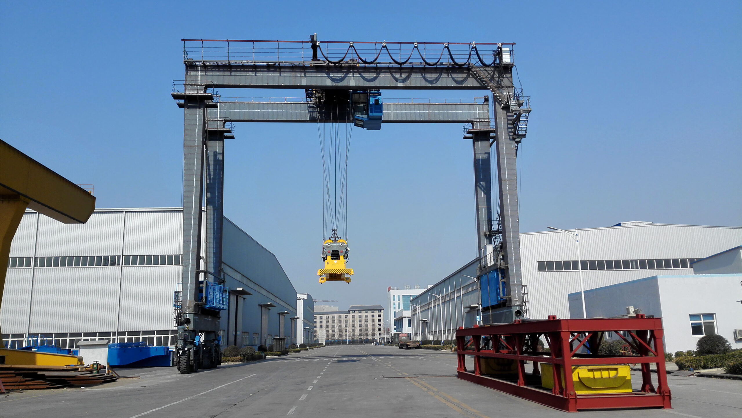

How to Design an Overhead Crane for Multi-Bay Workshops
Heavy-duty manufacturing, equipment processing and other industries generally adopt multi-span integrated workshops, which have large differences in cross-district working conditions and production functions, and complex material flow.Standardized cranes are difficult to adapt to differentiated operating needs, and they are prone to problems such as inconsistent loads, equipment interference, and blind spots in operations, which restrict production efficiency and have safety risks.
In this regard, the multi-span workshop bridge crane needs to be customized in combination with on-site working conditions, taking into account the needs of safety, efficiency, collaboration and expansion.This article details its complete engineering design plan in all directions, and provides a technical reference for the customization and transformation of plant lifting equipment.
How to Design an Overhead Crane for Multi-Bay Workshops
A multi-span workshop is an industrial plant composed of two or more parallel adjacent production areas, separated by columns and partitions, and unified into a complete production system. It is widely used in heavy manufacturing, shipbuilding, automobile assembly, steel processing and other heavy industry scenes.
Compared with a single-layer open workshop, the carrying capacity, headroom, structure size, and production functions of each cross-zone are significantly differentiated, and the cross-zone layout is compact, and the production can be operated independently or cooperatively linked.
The core goal of multi-span crane design
A set of qualified multi-span bridge crane systems must meet the five design indicators at the same time, taking into account safety, practicality and long-term performance.:
- Rated lifting weight: Each crane needs to match the corresponding maximum operating load across the area, reserve a reasonable safety margin, and fully consider additional loads such as spreaders, tooling, and dynamic operating impact.
- Global coverage: The operating scope of the equipment needs to cover all hoisting points in the workshop, completely eliminate blind spots in the operation, and avoid safety risks and production capacity bottlenecks such as manual assisted handling and illegal hoisting caused by lack of coverage.
- Operational efficiency: The operation logic of the crane needs to fit the production process, shorten the material handling path, reduce the waiting time of the equipment, and realize the seamless connection of materials in each process without interfering with the normal production rhythm.
- Operational safety: Multi-equipment, multi-cross-zone collaborative operation is prone to collisions, path conflicts and other problems. The design stage needs to configure a protection system in advance to avoid various risks of joint operations and optimize maintenance operating conditions.
- Expansion compatibility: Adapt to future development needs such as factory capacity upgrading, new equipment, and cross-district expansion. System upgrades can be achieved without large-scale demolition and transformation of existing equipment and structures.
Overall design process
The design of multi-span cranes follows a standardized and systematic process: first survey the physical layout of the workshop, clarify the production functions of each span, and then calculate the operating load and work level, and match the adapted crane model and cross-zone transfer plan.
Then complete the design of the structure, electrical, and control system, complete a full set of safety protection devices, and finally verify the collaborative operation ability of the entire system.All links are interlocking, and the early design decisions directly determine the performance and transformation costs of the later equipment, so rigorous engineering thinking must be adhered to throughout the process.
Assess the Workshop Layout Before Crane Design
Workshop site survey is the core foundation of crane design, which directly determines the accuracy and feasibility of the plan.There is hysteresis and error in the drawing data, and it is absolutely not a substitute for on-site survey. All design work must be based on on-site measured data.
Cross-zone size and net cross-zone surveying and mapping
Accurately measure the core parameters of each span: the effective net span between the columns, the total longitudinal length of the track, and the effective net height of the lowest obstacle from the ground to the top.For the renovation and expansion of old factories and workshops, the drawing parameters are often inconsistent with the actual situation on the site, and must be checked point by point to avoid errors in the selection of end beams and track positioning due to millimeter-level errors.
Among them, the net span of the span is the core parameter, which directly determines the span of the main beam of the crane, and at the same time affects the structural carrying pressure of the track beam and the plant column, which is the key basis for equipment selection and structural verification.
Positioning of each cross-production function
Workshops with different functions span regions, and have very different requirements for the tonnage, working level, control accuracy, and operating speed of the crane. Precise division of functions is a prerequisite for customized design.:
- Cross-zone production and processing: high-frequency hoisting of raw materials and semi-finished products, high operating frequency and large load-bearing movement, need to be adapted to high-level cranes, stable adaptation to continuous operating conditions.
- Equipment assembly across regions: The core requirements are precise alignment and smooth start and stop. It needs to be equipped with a frequency conversion speed control system to prevent load shaking and protect precision parts from damage.
- Cross-regional material warehousing: priority is given to ensuring global coverage and rapid transit, with low requirements for high-precision control and large tonnage loads, and a focus on improving operating efficiency.
- Equipment maintenance and maintenance across regions: flexible operation scenarios and fixed hoisting material specifications require strong crane adaptability, wide operating range, and flexible and convenient operation.
- Loading and unloading cross-zone: connecting indoor and outdoor operations, it is necessary to adapt to the rapid loading and unloading rhythm, and at the same time have a certain environmental adaptation ability to reduce the waiting time for vehicles to stop.
Cross-regional material flow combing
Comprehensively count the complete path of material entry, process transfer, and finished product out of the warehouse, and clarify the direction, frequency, and volume of material flow across regions.Determine whether cross-regional transshipment is a conventional core process or an occasional industry, in order to determine whether it is necessary to configure special programs such as cross-regional collaborative hoisting and docking transshipment platforms.
Clarify crane operation coverage requirements
Delineate the core hoisting area
Accurately mark all hoisting points in the workshop, including machine tool loading and unloading area, tooling assembly area, material stacking area, finished product delivery area, etc., to ensure that the hook can reach all operating points directly, and there is no blind spot in the operation.Operation blind spots will force workers to adopt illegal hoisting, manual material movement, etc., greatly increasing safety risks and production losses.
Investigation of blind spots and restricted areas
The limit stroke at both ends of the crane track and the structural limitations of the main beam end beam will lead to natural operating blind spots in the corners of the workshop and around the walls.If the production operation involves a blind area, it is necessary to completely eliminate the short board by optimizing the track stroke, improving the end beam structure, installing auxiliary equipment for cantilever crane, and adjusting the layout of the station.
Demand and frequency of transshipment across regions
Cross-zone material transfer is the core difficulty of multi-span crane design.For conventional process-based cross-regional transshipment, transshipment channels and collaborative operation intervals must be reserved during the design phase; occasional transshipment can simplify the configuration.At the same time, according to the frequency of daily and hourly transshipment, match the corresponding transshipment plan to avoid overallocation or insufficient capacity.
Verify the existing structural conditions of the plant
- Survey of column spacing: The layout of the column of the plant determines the support point and span of the track beam. If the spacing is too large, the specifications of the track beam need to be upgraded to improve the bearing capacity; for old factories with irregular spacing, the track arrangement needs to be optimized to ensure the stable operation of the equipment.
- Track support structure verification: It is necessary to fully verify the bearing capacity of the steel structure and column of the plant, taking into account the weight of the equipment, the static lifting load and the dynamic impact of start-stop braking.Old factories without the original load-bearing design must not rely on the main body of the factory to bear the load, and an independent support structure must be built.
- Top clearance and obstacle investigation: Comprehensively investigate roof trusses, pipelines, fire fighting, lighting and other top obstacles, accurately calculate the effective lifting height, and avoid the risk of interference and collision between obstacles and crane main beams and spreaders.
- Plant height calculation: The effective lifting height is the total floor height of the plant, deducting the height of the track beam, main beam, hoist structure and safety margin.In workshops with limited headroom, low-headroom hoists and lower-hanging cranes can be selected to fine-tune the structure and optimize the working space.
- Verification of supporting facilities: The layout of the crane shall not block or interfere with the original supporting systems such as fire protection, lighting, ventilation, and electrical. If the pipeline needs to be adjusted, it must be uniformly planned during the design phase to ensure the normal operation of the facilities.
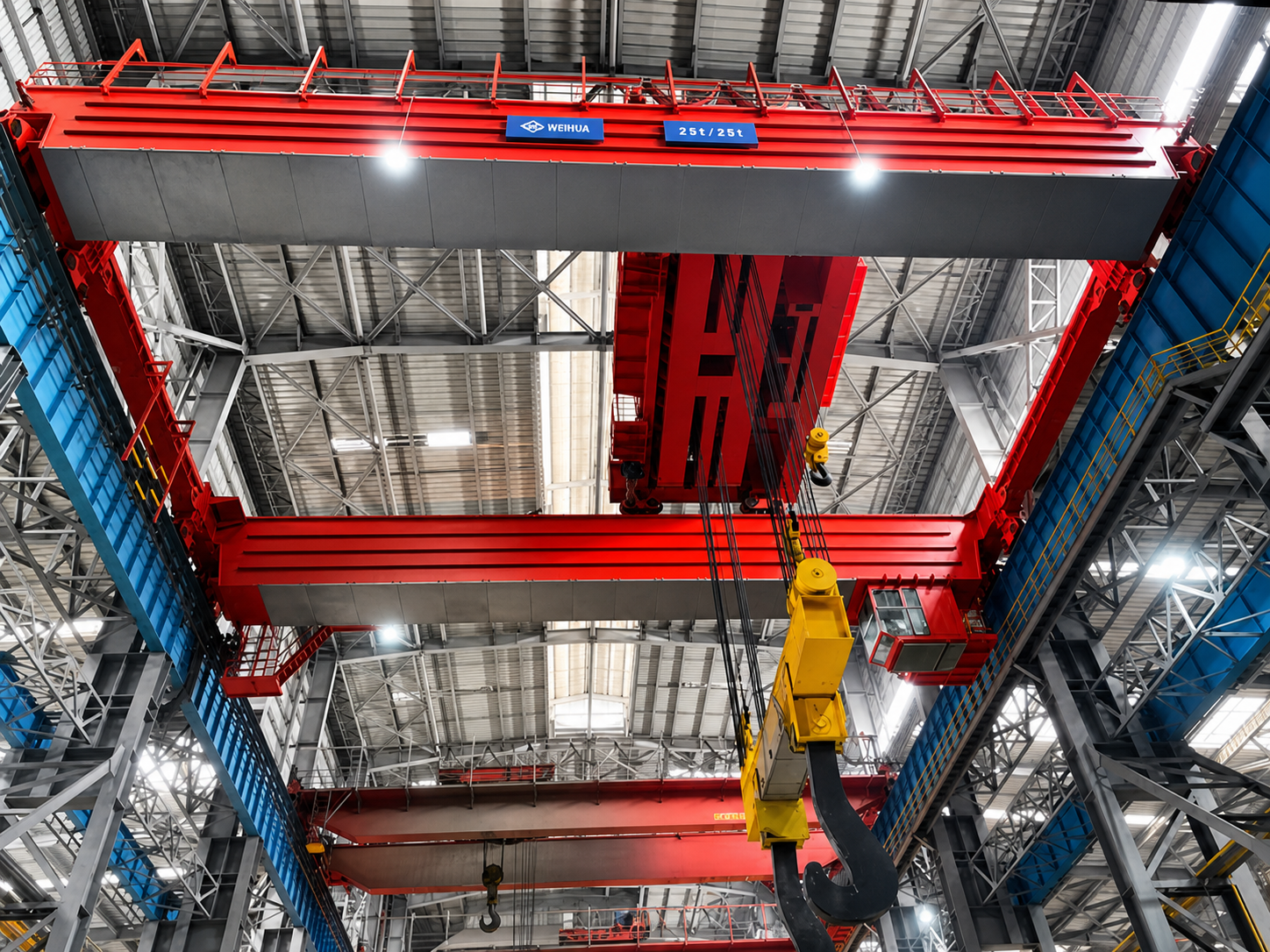
Determine the Required Overhead Crane Capacity
Load selection is the core decision-making link of crane design: selection is too small will cause safety hazards and cannot meet production needs; selection is too large to waste procurement costs, increase the load on the building structure, and increase the loss of operation and maintenance. Precise matching and on-demand selection are required.
Cross-zone static load accounting
Count the maximum weight of all hoisting materials step by step, including raw materials, semi-finished products, finished products, molds, tooling, large equipment accessories, etc. At the same time, the weight of all lower spreaders must be included, including lifting beams, vacuum suction cups, hanging chains, shackles, wire ropes and other accessories.
In engineering practice, many load calculations only count the weight of the workpiece and ignore the weight of the spreader, which will cause the actual operating load to exceed the rated parameters of the equipment and lay hidden dangers of overload.For example, a 10-ton workpiece with a special spreader of 800kg, the actual total operating load is 10.8 tons, and the tonnage of the equipment needs to be matched according to this standard.
Dynamic load and operating condition loss
- Dynamic impact force of start and stop: According to international crane design standards such as FEM, CMAA, ISO, etc., equipment start and stop, braking, and dynamic reclaiming will produce vertical and horizontal impact forces. Dynamic load coefficients need to be superimposed during design to avoid static load selection that cannot be adapted to dynamic operating scenarios.
- Precise alignment operation requirements: precision assembly and equipment alignment scenarios require long-term hovering of the load and fine-tuning of the position, and the corresponding control mode and load redundancy need to be matched to ensure the stability and accuracy of the operation.
- Matching the frequency of operations with the level of work: cranes that operate at high frequency and full load in a single day have a great difference in mechanical fatigue loss from cranes that operate sporadically every day.It is necessary to match the corresponding equipment working condition level according to the ISO working level and FEM working system, combined with the hoisting frequency and load utilization rate, rather than just referring to the maximum load.
- Reserve capacity upgrade margin: Combined with the factory's 10-20 year production capacity plan, reserve 10%-25% load redundancy to adapt to future equipment upgrades and capacity expansion needs, and avoid the problem of insufficient equipment performance in the short term and the need for overall replacement.
Choose the Right Crane Configuration for Multiple Bays
Single-girder and double-girder bridge cranes
Rated lifting weight adaptation
Single-girder bridge cranes are generally adapted to light-duty working conditions of 20 tons and below, and some customized models can reach 32 tons, which are suitable for light-duty assembly, warehousing, and sporadic maintenance operations;
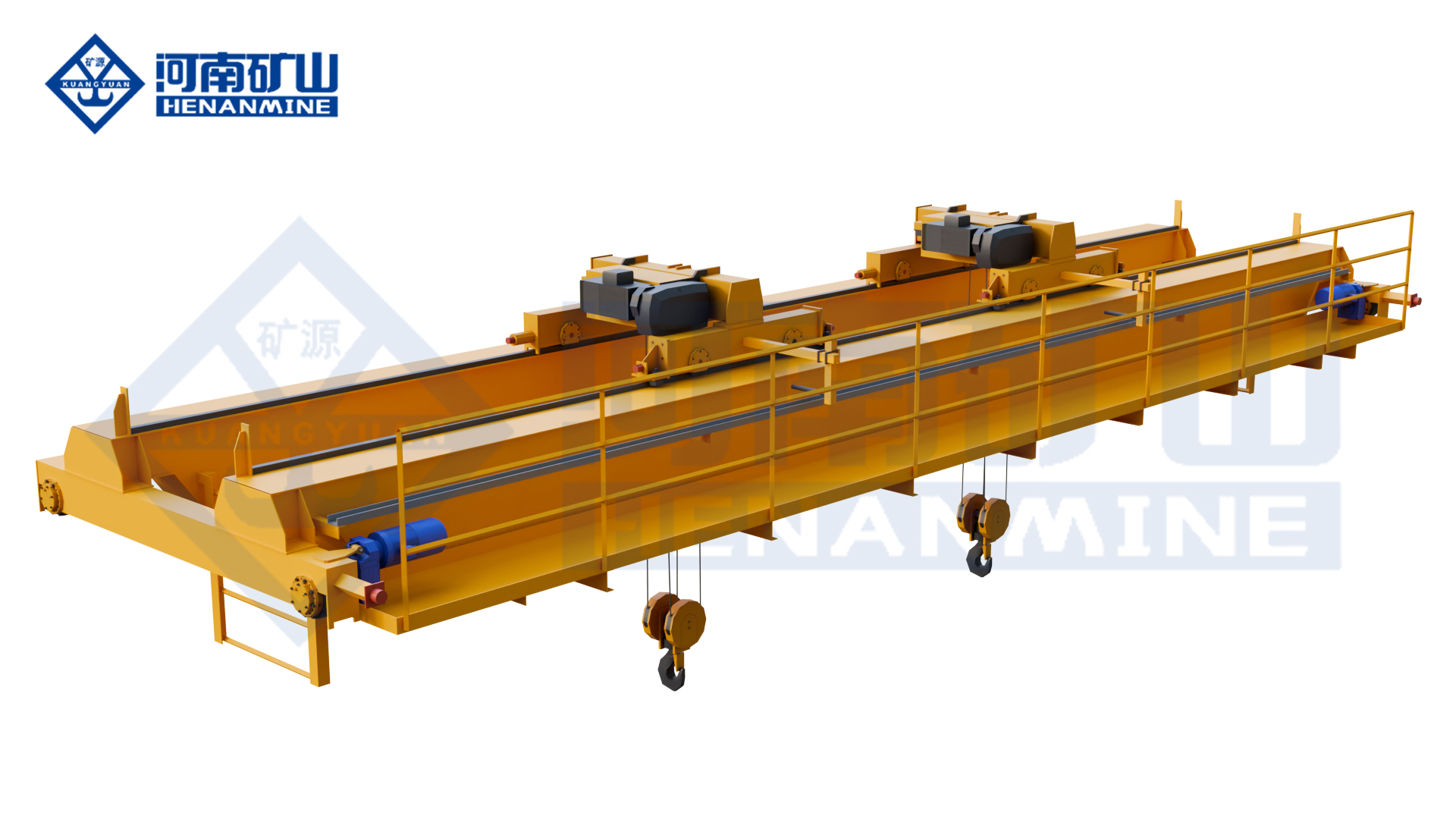
double-girder bridge cranes mainly focus on heavy-duty working conditions of more than 20 tons, and are suitable for all high-level and high-frequency operating scenarios. It is the first choice for heavy-duty processing and large-scale assembly.
Span and lifting height
The main beam of the double-girder crane has stronger rigidity and less deflection, can be adapted to large-span workshops, and has higher stability in heavy-duty operation; at the same time, the top-mounted trolley structure is used, and the hoist is installed between the double beams. Under the same height conditions, the effective lifting height is far better than that of a single-girder crane.
Top headroom adaptability
The single-girder crane hoist hangs down, the structure occupies a larger net height, and the effective lifting height is limited; the double-girder crane has a compact structure layout and a higher headroom utilization rate, which is the best choice for heavy-duty workshops with low headroom.
Operation and maintenance and service life
The single-girder crane has a simple structure and low procurement cost, but the maintenance and operation space is small, and the lower flange of the main beam is easily lost due to long-term heavy loads; the double-girder crane is equipped with maintenance walkways, convenient operation and maintenance, high structural strength, strong fatigue resistance, and longer service life throughout the life cycle, which is suitable for continuous industrial production.
Upper rail and lower rail crane systems
Structural carrying requirements
The end beam of the upper rail crane walks on the top of the track beam, with direct load transmission and uniform force, which is suitable for large-tonnage and high-frequency heavy-duty operations; the lower rail (suspension) crane is suspended at the bottom of the steel beam, and the force mode is special. It is only suitable for light loads and low-level working conditions.
Headroom utilization efficiency
Under the same operating conditions, the headroom utilization rate of the upper rail crane is higher and the effective lifting height is greater; the overall suspension of the lower rail equipment is sagging, taking up a lot of effective headroom, and the lifting height is obviously limited.
Adaptability of existing factories
For old factories where crane load-bearing conditions are not reserved, lower-rail suspension cranes can be used to install on roof steel beams without strengthening the column foundation; however, the bearing capacity of the roof structure must be verified in advance to eliminate safety hazards.The upper rail system is preferred for the newly built heavy-duty workshop, which has better stability and safety.
Design Crane Span, Runway Length, and Lifting Height
Precise selection of crane span
The span of the crane is the distance between the center lines of the two tracks. The core design principles are: adapt to the effective width of the workshop, cover all hoisting points, and avoid structural obstacles.
The span design needs to match the net width of the workshop to ensure that the hook can cover the whole area of the workshop through the end distance; at the same time, it is necessary to accurately avoid obstacles such as columns, equipment, and fixed tooling, and fine-tune the span of the main beam according to the location of the obstacles on the site to eliminate operational interference.
Track length design specification
- Longitudinal global coverage: The longitudinal length of the track needs to cover all loading and unloading points and operating stations in the workshop to ensure that the crane can complete all hoisting operations without moving tooling or manual assistance.
- Reserved end safety distance: According to industry standards, 500mm-1500mm end safety distance needs to be reserved at both ends of the crane track to adapt to the installation requirements of the end beam structure, buffer, and limit device to avoid equipment rushing to the top and colliding. This distance needs to be included in the total length of the track design.
- Docking loading and unloading points: material loading and unloading ports, cross-zone transfer points, and outdoor docking points must be included in the coverage of the track to achieve seamless material transfer and eliminate blind spots in operations.
Lifting height accounting and optimization
Effective lifting height is the core parameter to ensure the feasibility of the operation. The accounting needs to include four dimensions to eliminate estimation errors.:
- The maximum self-height of the workpiece;
- Spreader, tooling, wire rope suspension height;
- The minimum safety margin for the workpiece to cross obstacles;
- The equipment runs at a safe distance from the top.
If the standard model cannot meet the lifting needs, the effective height can be increased by selecting a low-clearance hoist, a compact main beam structure, and optimizing the layout of the spreader. It is strictly prohibited to reduce the safety margin in violation of regulations.
Plan Cross-Bay Material Transfer
Cross-regional material transfer is the core link of multi-cross workshop production. The unreasonable design of the transfer plan will directly form a production bottleneck and drag down the efficiency of the entire production line. It is the top priority in the design stage.
Definition of cross-zone transfer scenarios
When the production process requires workpieces to complete roughing, finishing, assembly, heat treatment, warehousing and other processes in different cross-regions in turn, a standardized cross-region transfer plan must be designed to adapt to the needs of normalized material flow.
Machine-to-machine docking and transfer mode
The most commonly used cross-zone transfer method is the collaborative docking of two machines: the upstream cross-zone crane transports the materials to the cross-zone boundary transfer area, and the downstream cross-zone crane relays the hoisting to complete the cross-zone transfer of materials.The plan requires that a common operating area be reserved across the boundary of the district, a passage hole be reserved for the partition wall, and a dual-machine anti-collision system be configured to ensure the safety of collaborative operations.
Design of transfer hole and work area
For the location of the cross-zone partition wall and column partition, a standardized transfer hole needs to be opened in advance. The size of the hole must be greater than the overall dimensions of the largest workpiece + spreader, and a safe passage margin should be reserved.The opening of the cave entrance needs to be completed in combination with structural verification. It is strictly forbidden to destroy the load-bearing structure of the building. The renovation of the old factory building needs to be strengthened in advance.
Dual-machine synchronous lifting scheme
For large-weight workpieces that cannot be carried by a single crane, a dual-machine synchronous lifting mode can be used. The two cranes work together and operate synchronously to increase the overall lifting load.
In this mode, special equipment that supports synchronous control must be selected, a load sharing monitoring system must be equipped, and special training for operators must be carried out, and it is forbidden to temporarily team up and lift at will.
Avoid cross-regional transit bottlenecks
The traffic capacity and operating efficiency of the transfer point need to match the maximum production capacity of the production line to avoid the accumulation and retention of materials at the boundary of the cross-zone.In the design stage, it is necessary to match the corresponding transfer channel and operating mode according to the transfer frequency and workpiece specifications to ensure smooth flow.
Coordinate Multiple Cranes and Avoid Operational Conflicts
Synchronous operation of multiple equipment across multiple workshops is extremely prone to path conflicts, equipment collisions, and job interference. Hardware protection + process control must be passed to achieve orderly and coordinated operation of equipment.
Crane anti-collision protection
Multi-equipment common rail and adjacent rail operations need to be equipped with intelligent anti-collision systems, relying on laser, ultrasonic, and encoder positioning technology, real-time monitoring of equipment spacing, automatic deceleration, emergency shutdown, and avoidance of collision risks.At the same time, both ends of the equipment need to be equipped with mechanical and electrical dual limit devices to prevent over-stroke operation.
In the design stage, it is necessary to clarify the minimum safety spacing of the equipment, and reserve a safety margin based on the braking distance and operating speed of the equipment to eliminate the risk of contact under extreme working conditions.
Multi-machine collaborative control logic
Multi-equipment common rail operations need to be divided into dedicated intervals, and the priority of operations should be clarified, and simultaneous operations of multiple machines in the same interval are prohibited.The conventional working conditions are independently controlled, and the equipment does not interfere with each other; the synchronous control system is enabled for the dual-machine lifting working conditions to ensure the accurate synchronization of operating parameters.
The wireless remote control system needs to be equipped with a dedicated identification code to eliminate the risk of cross-device serial control and false control; the wired handle has stronger control stability and is suitable for high-precision and high-safety operation scenarios.
Standardized control of hoisting path
For high-frequency conventional hoisting operations, formulate standardized hoisting paths, standardize equipment operation trajectories, and reduce the randomness of operations and the probability of conflicts.Simultaneous construction of multiple equipment is strictly prohibited in overlapping work intervals, and crane operation scheduling is incorporated into the overall production plan to achieve accurate matching of equipment operations and production processes, and reduce waiting time for vacancy.
Electrical and Control System Design
Power supply system configuration
Configure a dedicated power supply circuit according to the total power and peak load of the crane, adapt to the maximum power requirements of equipment lifting, cart, and trolley operation, and be compatible with frequency conversion braking and regenerative power feedback to ensure stable power supply and eliminate voltage fluctuations and overload tripping problems.
Power supply and transmission system selection
Three power supply modes are commonly used in industrial workshops, which can be adapted on demand:
- Sliding contact line power supply: strong stability, long service life, suitable for high-frequency and long-distance operation, is the mainstream solution for multi-span cranes;
- Cable towline power supply: suitable for short-stroke, clean environment workshop, regular wiring and easy maintenance;
- Cable reel power supply: suitable for ultra-long travel, outdoor connection scenes, can automatically receive and discharge cables, and has strong adaptability.
Frequency conversion speed control system
All series are equipped with a frequency conversion drive system (VFD) as standard, which realizes stepless speed regulation of crane lifting, cart and trolley, smooth start and stop, and no load shaking. It can not only protect precision workpieces, but also reduce mechanical impact, reduce equipment wear, and extend the service life of the whole machine.
Control system configuration
Conventional working conditions use wireless remote control, flexible operation, wide field of vision, suitable for multi-span and wide-range operations; high-precision alignment, high-risk operation scenarios can be used with wired handles for dual control.All remote control equipment comes with unique coding, anti-interference, and fault self-locking functions to prevent misoperation.
PLC intelligent control system
It adopts PLC programmable control system, integrates anti-collision, interval protection, overload protection, fault self-inspection, remote diagnosis and other functions, and can realize the automated operation of repetitive processes. At the same time, it supports docking with factory MES, WMS, and ERP systems to realize intelligent material management and equipment operation and maintenance monitoring.
Load monitoring and overload protection
Each crane comes standard with an intelligent load monitor, which displays the lifting weight in real time, triggers an early warning when it reaches 90%-95% of the rated load, and automatically locks the lifting action when it is overloaded, eliminating the risk of overloading operations from the root cause, and automatically retaining operation data for equipment operation and maintenance traceability.
Safety Design for Multi-Bay Overhead Cranes
Safety design runs through the whole process of equipment design, installation, operation, operation and maintenance, and is the core guarantee for multi-equipment collaborative operation. It is necessary to build an all-round and integrated safety protection system.
Core safety protection device
- Overload protection: fail-safe fail-safe design, automatically locks the equipment when the system fails to prevent overloading and hoisting;
- Emergency stop system: The fuselage and remote control handle are equipped with emergency stop buttons, which can instantly cut off all power and avoid danger in an emergency.;
- Multiple limit switches: lifting the upper and lower limits, the travel limits of the cart and the trolley, to prevent the collision accidents of rushing to the top and over-travel.;
- Intelligent anti-collision system: necessary for multi-device collaborative operation, automatically avoiding equipment interference;
- Sound and light early warning device: Sound and light alarms are automatically triggered when the equipment is running to remind on-site personnel to avoid and adapt to noisy industrial environments.
Safety maintenance channel design
In the design stage, a complete maintenance channel, operation and maintenance platform, and ladder walkway are reserved. The double-girder crane is equipped with an on-board maintenance walkway as standard to ensure that operation and maintenance personnel can safely access all components such as hoists, motors, rails, and electrical cabinets, and prevent illegal operations at high altitude.
Standardized maintenance plan
According to the working level and running time of the equipment, formulate normalized inspection, regular maintenance, and annual verification plans, clarify the maintenance process, division of responsibilities, and record standards, and ensure the long-term safe and stable operation of the equipment.
Compliance standard adaptation
The design, manufacture, installation and acceptance of the complete set of equipment are fully adapted to ISO 4301, FEM 1.001, CMAA 70/74, EN 13001, OSHA 1910.179 and domestic lifting machinery specifications, while meeting the local construction and safety standards of the project location.
Conclusion
The multi-span workshop bridge crane is designed as a comprehensive system project. It needs to be customized to match the span, lifting parameters, work level and operating process based on on-site working conditions and production needs, taking into account the collaborative operation of equipment and the later capacity expansion.
Accurate working condition evaluation and customized design can optimize equipment adaptability, improve handling efficiency, and reduce full-cycle operation and maintenance costs.Henan Mine Crane can provide customized design and manufacturing solutions for exclusive bridge cranes according to workshop layout and hoisting needs, which are suitable for the actual production conditions of the enterprise.