
40t Substation Transformer Gantry Cranes: Heavy Outdoor Lifting for Power Infrastructure
The difficulty of transformer hoisting lies not only in the weight of the equipment, but also in the limited space in the station, sensitive electrical facilities, and the requirements for stability when landing.40t Substation Transformer Gantry Cranes is an equipment solution for this kind of operation: through the ground-supported gantry, lifting mechanism and operating system, the lifting and horizontal transfer of heavy objects are completed within the specified area.Its applicability depends on the total lifting weight, operating coverage, foundation conditions and electrical safety boundaries, and cannot be judged only by the rated tonnage.
For EPC contractors and substation operation teams, the value of such cranes lies in the integration of transportation handover, equipment positioning and subsequent maintenance into reusable hoisting areas.This article focuses on conventional gantry cranes driven by electric hoists or lifting trolleys; hydraulic jacking gantry frames have different structures and operating methods, and the configuration conditions here cannot be directly applied.
What Is a 40t Substation Transformer Gantry Crane?
Main Structure and Operating Principle
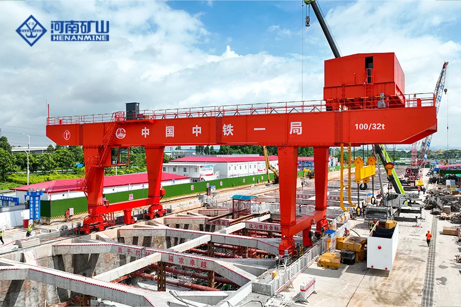
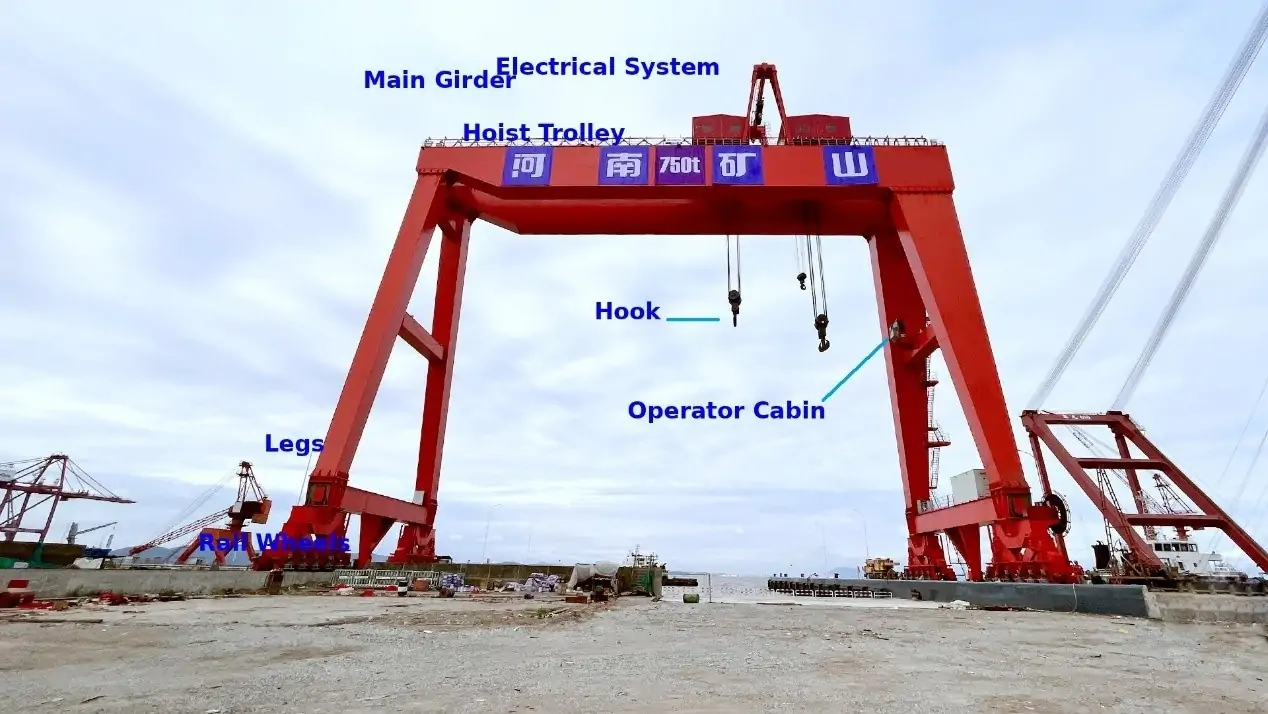
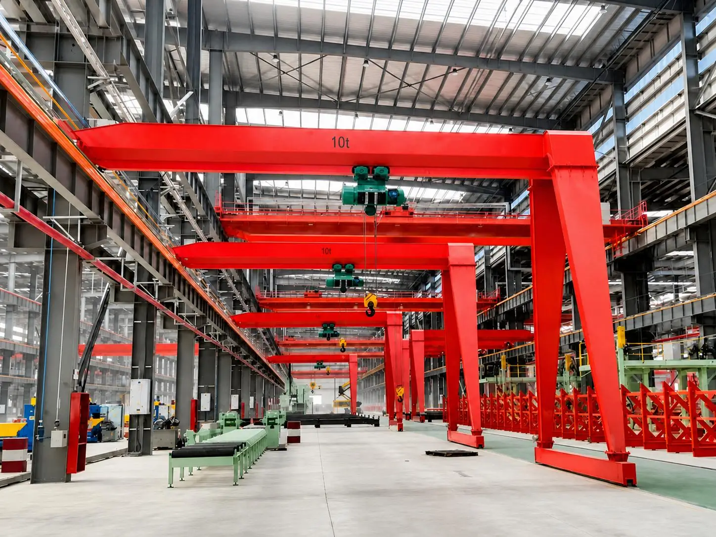
A typical structure consists of a main beam, outriggers, a lower end beam or a walking trolley, a lifting mechanism and an operating system.The hoisting is transmitted to the main beam through hooks and wire ropes, and then enters the foundation through outriggers, wheels and track foundations.The lifting mechanism is responsible for vertical movement, the electric hoist or trolley moves laterally along the main beam, and the whole machine runs vertically along the specified path to form a working coverage.
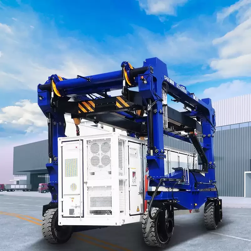
Door-type structures usually do not rely on the elevated rail beams in the upper part of the plant, but they still require designed ground support.Orbital door machines rely on the track to maintain a geometric relationship with the foundation; tire door machines involve tire load, steering and road conditions, and the two cannot be regarded as the same configuration.The definition of conventional gantry cranes in the United States OSHA 1910.179 also emphasizes that the main beam is supported by outriggers and moves along the track or other operating channels.
Why Choose a 40-Ton Lifting Capacity?
40t represents the rated lifting weight under the specified conditions, which is understood in metric tons in this article.It can cover the installation, replacement and maintenance hoisting of some transformers and supporting equipment, but it does not mean that all substations are suitable for this capacity.The delivery status of the equipment, the insulating oil, the installed accessories and the weight of the spreader will all change the actual lifting weight, and the weight cannot be directly estimated based on the voltage level.
The reasonable premise for choosing 40t Substation Transformer Gantry Cranes is that the heaviest operating load is within the approved capacity of the equipment and matches the expected operating frequency.The safety factor in the design is not an additional lifting weight that can be called on site; if a heavier transformer may be replaced in the future of the project, this change should be evaluated during the selection phase, rather than relying on overload to complete the operation.
Gantry Crane vs. Other Transformer Lifting Methods
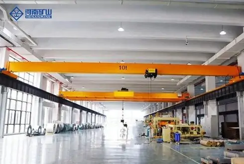
Gantry cranes are suitable for repeated lifting and transshipment in a clear coverage area, especially for outdoor sites that lack permanent elevated track support.Fixed bridge cranes usually require corresponding elevated operating structures; truck cranes belong to a class of mobile cranes and can adjust the station position, but the ability is affected by the actual amplitude, arm length, outrigger configuration and hoisting direction and other conditions.
There are also space restrictions on the door machine: the outriggers need access, the main beam needs clearance above, and the hook is close to the limit.Narrow entrances, low busbars, or frequent cross-field transfers may make other solutions more suitable.The hydraulic door frame and jacking slip system can be used in certain restricted scenarios, but its support, synchronous control and load transfer process need to be designed separately and cannot be regarded as a direct alternative configuration to ordinary door machines.
Key Applications in Power Infrastructure Projects
Power Transformer Installation at Outdoor Substations
During the installation of a new substation, the door machine can lift the transformer from the transport vehicle or temporary storage location within the design coverage, and then move it to the prepared foundation.The parking position of the transport vehicle, the net distance between the legs and the actual reachable area of the hook must be connected to each other; if the unloading point falls outside the coverage area, even if the tonnage of the whole machine is sufficient, the scheduled handover cannot be completed.
The installation process is also constrained by the foundation elevation, positioning components and protruding parts of the equipment.The fact that the transformer can be accommodated under the main beam does not mean that the hoisting path has been smooth: the hoisting beam, rigging, casing and radiator may all become control dimensions.The transportation, lifting and installation teams share the same set of location and elevation information, so as to reduce the situation where path conflicts are only discovered after the equipment is floating.
Transformer Replacement and Maintenance
The replacement operation includes the removal of old equipment, the access of new equipment, and temporary storage. Therefore, the coverage cannot only be designed around the final foundation.A reasonably arranged door machine can reduce unnecessary secondary reverse transportation in the coverage area, and make the connection between disassembly, maintenance and reinstallation clearer; however, the actual power failure time still depends on the complete process of electrical isolation, accessory disassembly and acceptance.
Even if the access door machine is used less frequently, it will be exposed to rain, dust and temperature differences for a long time.Corrosion, brake component status and electrical moisture during deactivation will not disappear due to low frequency of use.Maintenance arrangements therefore depend on both operating load and environmental exposure, and inspections before reactivation are also part of equipment availability.
Lifting Other Heavy Substation Equipment
Reactors, transformer accessories, and designated electrical components in the same operating area may also be handled by the door machine, but each load requires its own weight, center of gravity, and hanging point information.The power industry application data of the American manufacturer Shuttlelift lists door machine handling objects such as transformers, generator housings, and substation modules, indicating that such equipment has a variety of application scenarios, which does not mean that any model can complete all tasks.
In transformer manufacturing plants or power equipment assembly plants, repeated handling may also involve inter-station transfer and loading.Compared with occasional maintenance, this kind of task will increase the number of starts and stops of the organization and the cumulative load, and the work level needs to be re-evaluated when selecting the type.Two cranes with the same rated tonnage may not be suitable for the same production cycle.
How to Specify a 40t Outdoor Gantry Crane
Rated Capacity and Actual Lifting Load
For the load accounting of 40t Substation Transformer Gantry Cranes, it is first necessary to clarify what weight is suspended under the hook.The transformer body, accessories for hoisting with the equipment, hanging beams, slings, shackles and other hoisting accessories are all within the scope of verification; the accounting methods of items such as hook groups in different load gauges are subject to the manufacturer's documents to avoid missed calculations or repeated deductions.
Assuming that in a certain operation, the transformer and accompanying accessories are 36t, and the total hanging beam and rigging are 2t, the total load under the hook is 38t.This is only an assumption used to explain the calculated caliber and does not constitute job approval.The remaining 2t is not allowed to increase the margin of impact or side pull. In the end, it is still necessary to check the actual lifting configuration, the position of the hook and the use restrictions specified in the project.
Span, Lifting Height, and Working Coverage
The span of a rail-type door machine is usually defined by the distance between the centerlines of the tracks on both sides, and cannot be directly regarded as the net width of passage between the legs.The proximity distance of the end of the trolley, the shape of the outriggers and on-site obstacles will further reduce the effective hoisting area.Therefore, the general layout plan needs to show the shape of the structure, the traffic channel and the boundary of the hook reachable separately.
The lifting height is determined by the equipment's ground clearance requirements, the height of the hanging point, the height occupied by the rigging and the hanging beam, and the structural size of the hook group and the trolley must be checked.After adding a hanging beam in a certain scheme, although the rigging arrangement is improved, the available headroom may be compressed.The longitudinal operating distance must also cover unloading, installation, maintenance and temporary storage locations, not just connecting the two foundations.
To cover the verification, the complete shape of the equipment must also be considered.Even if the center of the hook can reach the designated point, the edge of the transformer may still touch the outriggers, fences, or adjacent facilities.For equipment with asymmetric shape, the center of gravity and the geometric center may not coincide. Therefore, the path map needs to reflect the actual hoisting posture and protruding parts, and only one hook center line cannot be drawn.
Hoisting Speed and Positioning Accuracy
When the transformer approaches the foundation, the control focus shifts from improving efficiency to stable placement.Two-speed lifting or frequency conversion control can provide lower speed and softer start and stop, but positioning performance is also affected by braking response, structural deformation, wire rope elasticity and lifting swing.Therefore, the configuration of the inverter itself does not prove that the equipment has a fixed positioning accuracy.
Low-speed control should also cover the necessary horizontal and vertical movements to avoid slow enough vertical direction and sudden start and stop of horizontal operation.The speed range, operating response, and braking performance can be included in the acceptance conditions; the final positioning error needs to be evaluated in combination with the hoisting method, observation conditions, and basic interface, and cannot be represented by only one motor parameter.
Structural Design and Ground Conditions
The ground support bears the reaction force formed by the crane's own weight and the lifting load, and 40t cannot be simply evenly distributed to all wheels.When the trolley is close to one side, the wheel pressure on each side will change, and the operation, braking and wind load will also affect the design working conditions.The civil interface therefore requires the maximum wheel pressure, wheel track, track gauge and related horizontal action data, not just the total weight of the equipment.
The state of the site after the rain is particularly worthy of attention.Stagnant water may expose insufficient drainage, or it may be accompanied by local soil softening, causing changes in the original supporting conditions.Continuous arrangements need to be formed for track foundation, peripheral drainage and maintenance inspections; for tire-type schemes, the entire on-load driving path belongs to the scope of support verification, and the lifting position and final parking point cannot be verified only.
Local weak points may form in the cable ditches, underground pipelines, backfill areas and ditch covers of substations.The laying of concrete does not mean that the crane support requirements have been met, and the uneven settlement of the track may also lead to increased rail gnawing and operating resistance.U.S. construction rules OSHA 1926.1402 emphasize ground support, drainage, leveling and underground hazard information; other areas should adopt locally applicable design and construction requirements.
The design of outdoor structures also involves wind, temperature and corrosive environments during work and shutdown.The main beam and hoisting with a large windward area will pass the horizontal effect into the outriggers and foundation; rainwater accumulation and coating damage may gradually weaken the state of the components.Corresponding measures need to be implemented on the structure, drainage, anticorrosive system and maintenance channels at the same time. Adding only one topcoat is not enough to solve all the problems.
Power Supply and Electrical Protection
The on-site voltage, frequency, power supply capacity and line length need to be matched with the lifting and operating mechanism.The cable reel, sliding contact power supply or towing cable scheme will also affect the operating range, maintenance location and vehicle traffic.The protection level of the outdoor electrical box should be determined in combination with rain, dust and installation location, and the problems of condensation and heat dissipation in the box also need to be considered separately.
Protective grounding, fault protection, and isolatable power supply devices belong to the electrical design content of the whole machine, but crane grounding cannot replace the safe distance between the live facility and the live facility.Wireless remote control is conducive to the operator to choose the observation position, but it cannot eliminate the blind spot; the safety response, emergency stop and unified command after the signal is lost must still be clarified in the control plan.
Safety Requirements for Heavy Transformer Lifting
Load Stability and Lifting Points
The transformer hanging point must be confirmed according to the manufacturer's drawings of the corresponding equipment.The lugs used for the lid, body or accessories cannot be used for hoisting the whole machine without confirmation.The center of gravity bias will change the force of each sling branch, and the four hanging points do not mean that each hanging point always bears a quarter of the load; the geometric relationship and length deviation of the rigging may affect the distribution.
The closer the sling is to the level, the greater the branch tension and horizontal force generated under the same vertical load.A suitable hanging beam can improve the direction of force and reduce the extrusion of the shell, but its own weight and height also enter the selection calculation.Schneider Electric's low-voltage dry transformer handling instructions show the importance of the angle between the hanging beam and the rigging; the specific angle belongs to the product description and cannot be directly used as a general requirement for large oil-immersed transformers.
The working load limit of the rigging is also related to the connection method, angle and manufacturer's conditions of use, and the nameplate values of each branch cannot be added up.After the force is established, the equilibrium state, the connection of the hanging point and whether there is any resistance to the load shall be verified in accordance with the approval procedures.If the equipment is still connected to the foundation or other components, directly increasing the lifting force may introduce additional loads. The rated tonnage does not eliminate this risk.
Essential Crane Safety Devices
Overload protection, lifting limit, operating limit, emergency stop and braking systems are aimed at different risks.Overload protection limits abnormal loads, the rising limit prevents the hook group from crossing the range, and the operating limit controls the equipment to approach the end of the stroke; the lower limit and other protection configurations are determined in combination with the mechanism design and applicable standards.These devices cannot replace each other, nor can they replace the normal daily parking control with a limit switch.
For 40t Substation Transformer Gantry Cranes, sound and light warnings, anti-collision, and area restrictions can be configured according to the intersection of people and vehicles and adjacent equipment, but the protection effect depends on the correct settings and function checks.The safety device also cannot make the wrong hanging point or the path that has not been evaluated acceptable.When it comes to live facilities, the entire range of motion of equipment, slings, and hoisting must be included in the electrical operation boundary.
Wind and Weather Management
The influence of wind on hoisting includes the swing of the hoisting, the lateral force of the structure, and the risk of movement of the whole machine after shutdown.If two pieces of equipment of the same weight have different windward areas and shapes, their windward performance may be significantly different.Therefore, it is not appropriate to give a unified lifting wind speed for all 40t door machines. The working limit value should come from the manufacturer's documents and be determined in combination with the specific lifting and on-site lifting plan.
Wind resistance during shutdown and wind limit during operation are two problems.Rail clamps, anchoring devices, or other parking fixing measures need to be designed in conjunction with the whole machine and the foundation, and the walking brakes cannot assume all wind resistance functions without verification.Weather management should also reserve time for safe loading and fixing of equipment; the U.S. construction rule OSHA 1926.1417 also requires that operations be adjusted for the impact of wind and snow on stability and rated capacity.
On-site monitoring cannot only look at the weather forecast before the start of construction.Wind gusts may change the lifting attitude, rainfall and low visibility may affect command and observation, and thunderstorms involve electrical risks to personnel and equipment.The hoisting plan needs to clarify the abort conditions and the available landing location, so that there is an exit path that can be executed when the weather changes.
Standards, Inspection, and Commissioning
Applicable regulations depend on the location of the project, the type of equipment and the usage scenario.The requirements for bridge and gantry cranes in the general industry in the United States are different from the scope of application of the construction crane clause, and a certain clause cannot be directly used as the basis for the unified certification of global projects.The risk of live lines near substations also involves special electrical regulations, such as the work area assessment and intrusion prevention measures stipulated in OSHA 1926.1408 in the United States.
The acceptance before being put into use shall cover the installation quality, track status, lifting and operating functions, braking and protection devices, and carry out load tests in accordance with applicable requirements.The test load, method and qualification conditions come from the corresponding standards and manufacturer procedures, and a ratio cannot be applied on its own.Rated capability documents, test records, operation and maintenance manuals, and personnel training together constitute the delivery content. Follow-up inspections should also consider the deactivation time and outdoor environment.
40t Gantry Crane vs. Mobile Crane for Substation Projects
When comparing 40t Substation Transformer Gantry Cranes with mobile cranes, the two solutions should first bear the same starting point, end point, and complete hoisting path.The nominal maximum tonnage of a truck crane usually only corresponds to a specific configuration and cannot be regarded as the available capacity at all amplitudes; the door crane needs to prove that the target location is within the approved hook coverage and rated capacity range.
| Comparison factor | 40t gantry crane | Mobile crane |
| Working area | Defined lifting zone within approved travel limits | Flexible positioning within access and reach limits |
| Infrastructure | Engineered ground support and travel path | Engineered setup area and ground support |
| Capacity assessment | Rated load for the approved configuration and hook position | Load chart for radius, boom and setup configuration |
| Overhead clearance | Gantry height, hook geometry and rigging headroom | Boom geometry, rigging headroom and obstructions |
| Repeated lifting | Suited to repeated lifts within its coverage | Can be repositioned for separate lifting locations |
| Best-fit scenario | Planned operations in a dedicated area | Projects requiring flexible setup locations |
The economy also depends on the way it is used.Dedicated door machines involve foundation, installation, power supply and continuous maintenance, while mobile cranes involve entry and exit, station preparation and leasing arrangements.Tasks with high frequency and stable path may be more able to realize the value of the door machine; projects with one-time or decentralized hoisting points may be more suitable for mobile equipment, and ultimately it is still determined by the site geometry, load gauge, ground conditions and complete hoisting plan.
Customization Options for Project-Specific Requirements
Customization first revolves around the span, lifting height and operating path, and then matches the configuration of the electric hoist or lifting trolley.Expanding the span may change the weight, stiffness and wheel pressure of the main beam, while increasing the height of the structure may increase wind action and affect the headroom of adjacent facilities. Therefore, each dimensional adjustment needs to be calculated at the interface between the whole machine and the civil construction, and cannot be regarded as an independent parameter.
The control method can choose a handle, wireless remote control or other approved scheme, and configure warnings, monitoring, and regional restrictions in combination with the observation location.Outdoor options also include environmentally friendly anticorrosive systems, electrical boxes, and weather-resistant components.If the project wants to move across regions, it needs to clarify the differences between the orbital and tire schemes, and it cannot only add steering requirements to conventional orbital door machines.
Modular delivery is conducive to adapting to transportation and on-site assembly conditions, but the module size, transportation route, assembly site and auxiliary crane capacity must be connected in advance.The main beam connection, installation tolerances, on-site inspection and commissioning scope should also be included in the contract technical documents, otherwise the convenience of transportation may be converted into additional work during the on-site installation phase.
What EPC Contractors Should Confirm Before Ordering
The key to EPC technology procurement is to allow transformers, cranes, civil engineering and electrical majors to use consistent data.The weight and center of gravity of the equipment, the hanging point map, the plane and elevation of the station area, foundation data, underground facilities and power supply conditions together constitute the selection input.When the data changes, it should be able to track its impact on the total lifting weight, coverage and basic reaction force.
The operating frequency, load distribution and maintenance reachability also need to be determined before ordering.Occasional replacement and continuous assembly may correspond to different working levels, and only replacing the lifting motor in the later stage may not change the allowable working intensity of the whole machine.Quotation comparison should therefore cover the same technical boundaries, including outdoor conditions, protection configuration, spare parts and after-sales support, rather than just comparing tonnage and span.
The delivery arrangement also needs to clarify who will provide the track foundation, power supply interface, auxiliary installation equipment and test load, and who will be responsible for commissioning, training and acceptance.The arrival date of the equipment is not the same as the date when it can be put into use; only by including these responsibilities and required documents in the schedule can the time to wait for civil construction or test conditions after the arrival be reduced.
Conclusion
The 40t substation gantry crane is suitable for well-planned outdoor heavy equipment hoisting operations.When selecting the type, it is necessary to comprehensively consider the lifting weight, spreader, operating headroom, ground carrying, outdoor protection and control system, and determine the equipment configuration based on the hanging point map and the layout of the station area.Henan Mine Crane can provide customized gantry crane solutions according to project working conditions to meet the lifting and maintenance needs of substation equipment.