
50t Cantilever Gantry Cranes: Overhang Structural Calculation and Side Bay Loading
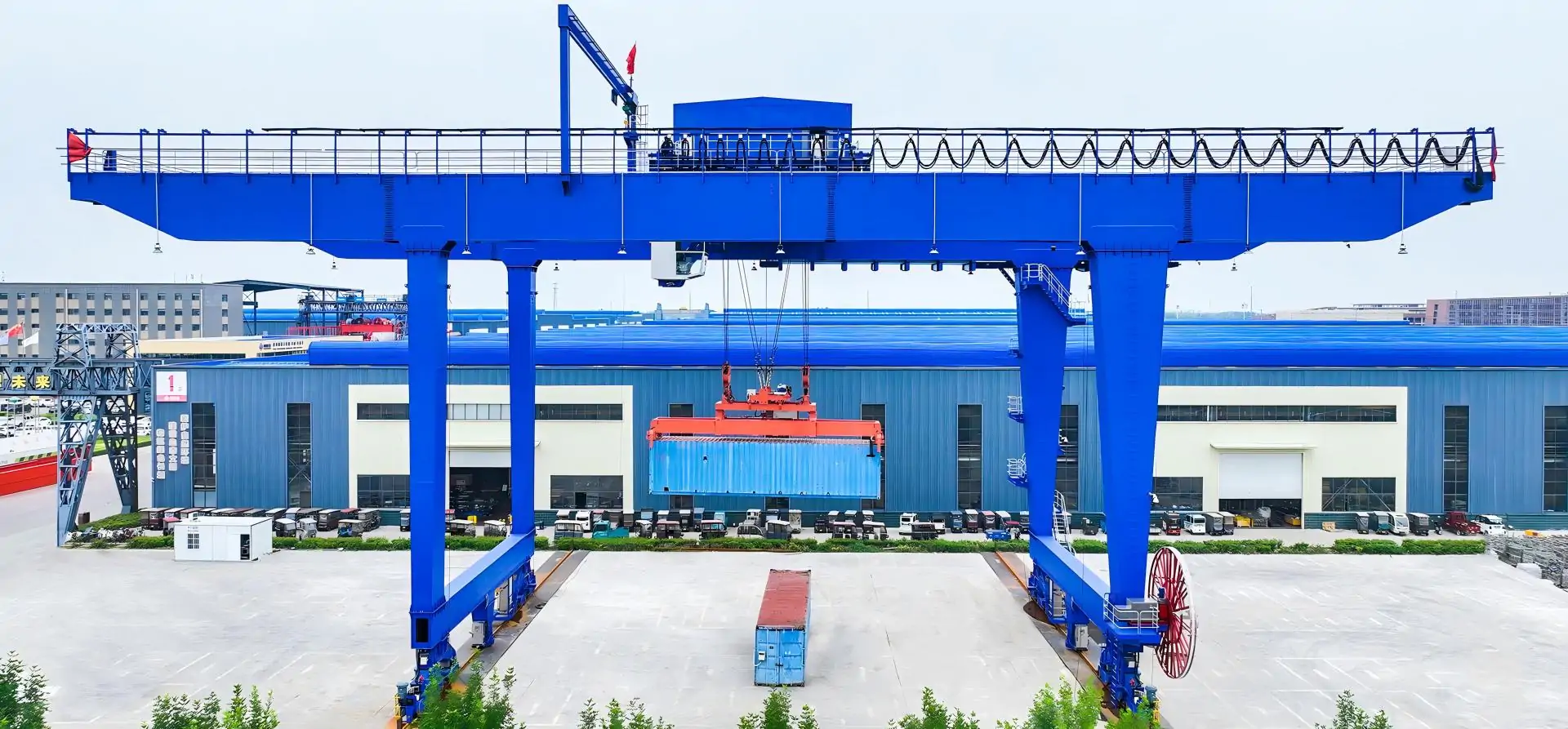
The 50t Cantilever Gantry Cranes extends the scope of hook operation beyond the gantry legs, making it suitable for picking and unloading heavy objects from trucks, steel depots, or adjacent production areas.However, the rated lifting weight of 50 t cannot determine the length of the cantilever alone.The longer the extension, the greater the bending moment of the root, the deflection of the end, and the pressure of the near wheel, and the smaller the reaction force of the far wheel.Therefore, a reasonable design must answer three questions at the same time: whether the main beam can withstand the load, whether the position of the hook can be maintained controllable, and whether the whole machine and the track foundation can maintain stability under partial load.
Understanding the Structure of a 50t Cantilever Gantry Crane
Main Structural Components
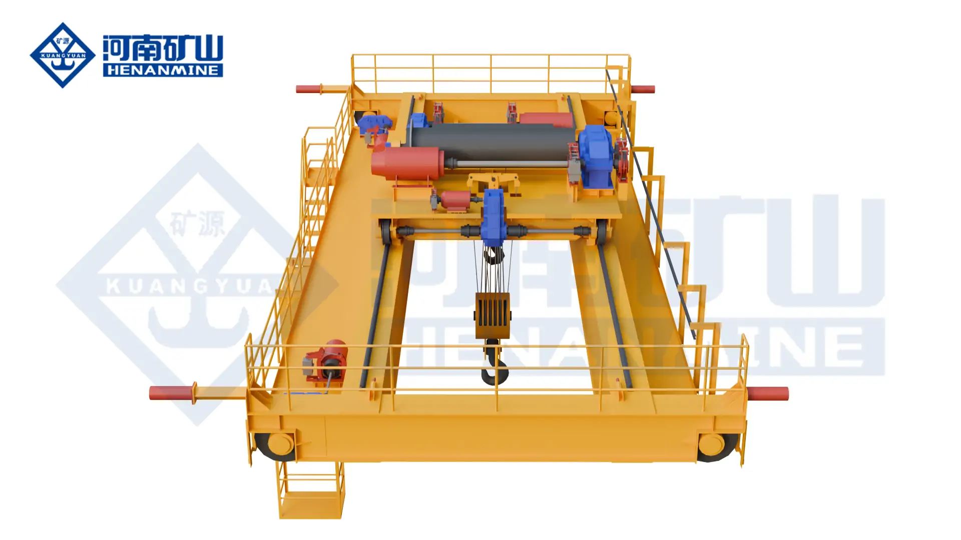
The main beam of the gantry crane spans the outriggers on both sides, and the end of the beam crosses the part of the outriggers to form a cantilever.The trolley and the 50 t lifting mechanism run along the main beam, and the lifting weight is passed into the main beam through the hook, wire rope, reel, trolley frame and trolley wheel.The main beam then transmits its action to the outriggers, the lower beam, the cart operating mechanism and the wheels, and finally the track and foundation bear it.
The end beam and the transverse connection keep the various parts of the beam body working together, and the oblique support limits the lateral deformation of the gantry under the action of operation, braking and wind.For 50t Cantilever Gantry Cranes, any local reinforcement must obey the full load path.Only add steel plates to the root of the cantilever. If the outrigger connection, wheel set or foundation are not checked synchronously, the force problem at the machine level cannot be solved.
Single-Cantilever vs. Double-Cantilever Configurations
The single cantilever only serves one side of the gantry, which is suitable for projects where transportation vehicles are fixed on the same side or where there is a building boundary on the other side of the site.The double cantilever can pick up and place goods on both sides to expand the coverage of the site, but the beam body is longer and the weight is greater, and the trolley limit and safety clearance must be set in both directions.
The double cantilever does not mean that the operating load is automatically balanced.When the trolley is running to the extension section on one side, the cantilever on the other side can only participate in the overall balance with its own weight, and the weight that does not yet exist cannot be used as a counterweight.The choice of plan should be determined based on the real logistics flow direction, track position, yard width and operating frequency, rather than simply pursuing the maximum geometric coverage.
Main Span, Overhang Length, and Side Bay Layout
The main span is the horizontal distance between the center lines of the two cart tracks.The length of the cantilever is usually calculated from the cross-section of the adjacent support line or the specified structure to the beam end, and the effective stroke of the hook must also deduct the trolley wheel track, end buffer, stop position and the center bias of the hook.Therefore, the physical outer elongation is not equal to the available hoisting range.
The side span working envelope should be based on the center of gravity of the cargo and the trajectory of the spreader.The width of the truck, the location of the loading and unloading point, the clearance of the outriggers, the swing space of the cargo, and the no-entry zone will all change the required extension.When the arrangement adjustment can move the farthest pickup point in the direction of the outrigger, the structural requirements tend to decrease significantly, which is usually more effective than first determining the long cantilever and then passively thickening the main beam.
Overhang Structural Calculation: Key Engineering Parameters
Design Inputs for a 50t Gantry Crane
Before the calculation begins, it should be clarified whether the rated lifting weight includes the spreader, and obtain the total weight of the trolley, the number of wheels, the wheel track and the position of each wheel.The structural input includes the main span, the length of the cantilever, the cross-section of the main beam, the material grade, the thickness, the stiffening system, the outrigger form, the connection stiffness, and the weight of each part of the whole machine.Civil construction input includes track model, foundation stiffness, allowable settlement and foundation carrying conditions.
Operating data is also design input.The working level, load spectrum, number of cycles per hour, life expectancy, lifting and operating speed will affect the power and fatigue check; outdoor wind, temperature, corrosive environment and possible snow cover will change the load combination and material protection requirements.50t Cantilever Gantry Cranes must define these conditions under the same set of applicable standards to avoid mixing incompatible coefficients and acceptance criteria.
Calculating the Cantilever Bending Moment
The bending moment of the cantilever root is determined by the size of the load and the horizontal distance from the load to the root.When the same lifting weight moves outward, the force arm increases, and the demand for root structure will also rise.In the calculation, not only the suspended object should be considered, but also the weight of the spreader, trolley, lifting mechanism and the cantilever itself should be included, and the operating impact, mechanism acceleration and deceleration, and other possible simultaneous effects should be handled in accordance with the project standards.
The real trolley transmits force to the main beam through multiple wheels, and the position of the hook and the wheel position of the trolley are not the same coordinates.Under full load conditions near the outer end, a larger overall bending moment of the root is usually formed, but the control position of local wheel pressure, web stress, or weld stress may be different.The design analysis should allow the trolley to move along all allowable strokes to form an envelope of bending moment, shear force and local effects, and then identify the most unfavorable working conditions of each verification project separately.
Shear Force, Bending Stress, and Section Selection
The nominal bending stress of the main beam depends on the bending moment and the ability of the cross-section to resist bending.The root shear force is formed by the concentrated load on the cantilever and the distributed load, and the web must also withstand the local action near the wheel pressure of the trolley.In addition to the overall bending of the box-shaped main beam, torsion may also occur due to orbital eccentricity, hook bias, or uneven distribution of the two main beams.
Cross-section design cannot only rely on improving material strength.Increasing the beam height can usually effectively improve the bending stiffness and cross-section modulus. Thickening the flange helps to improve the bending bearing capacity. Thickening the web or arranging stiffeners can improve shear and local stability, but each measure will change its own weight, manufacturing difficulty and welding details.The local buckling of the compressed flange, the shear buckling of the web, the wheel pressure bearing and the overall stability must be verified separately.
The root of the cantilever and the inner span area may withstand bending moments in different directions, and the tension and pressure state of the flange will vary with the position of the trolley.Plate thickness mutations, stiffener ends, diaphragm connections and discontinuous welds are prone to stress concentration.Local reinforcement should cause the force flow to spread smoothly to the main structure, and suddenly terminated thick plates or rigid components may instead form new fatigue weak points in adjacent locations.
Deflection and Serviceability Requirements
The deformation of the end of the cantilever is very sensitive to external elongation, so the addition of a small section of the cantilever may also cause a significant change in the position of the hook.Increasing the bending stiffness of the beam body can limit the local deflection, but the cantilever root of the real gantry is not absolutely fixed, and the bending of the main span, the rotation of the outriggers, the connection compliance and the foundation settlement will also produce additional displacement.Only analyzing the extension section itself is easy to underestimate the actual deformation.
Excessive deflection will reduce the positioning accuracy of the hook, cause the trolley track to form a significant slope, and increase the tendency of the cargo to swing after lifting.The use performance verification requires the use of the specified service load combination, and explains the measurement reference, pre-arch, and self-weight deformation treatment methods.The limits used by different projects and standards may be different, and a single span-length ratio cannot be regarded as a common criterion for all equipment.
Fatigue and Repeated Loading
Fatigue focuses on the stress range and the number of cycles, not just the maximum stress generated by a hoisting.When the trolley enters the cantilever from the main span and then returns, the roots, track connections, and cross-section transitions will undergo repeated stress changes.Even if a single load does not yield the material, enough cycles may still cause cracks to sprout from welding toes, welding roots, or geometric mutations.
Fatigue analysis should combine the working level and the actual load spectrum to determine the stress course corresponding to different lifting weights, positions and cycles, and then evaluate the cumulative damage according to the applicable detailed categories.The use of higher-strength steel does not automatically improve the fatigue capacity of welding details.Continuous force flow, reasonable weld direction, stable manufacturing quality and achievable inspection plans are equally important.
Side Bay Loading: Load Distribution and Stability Analysis
What Is Side Bay Loading?
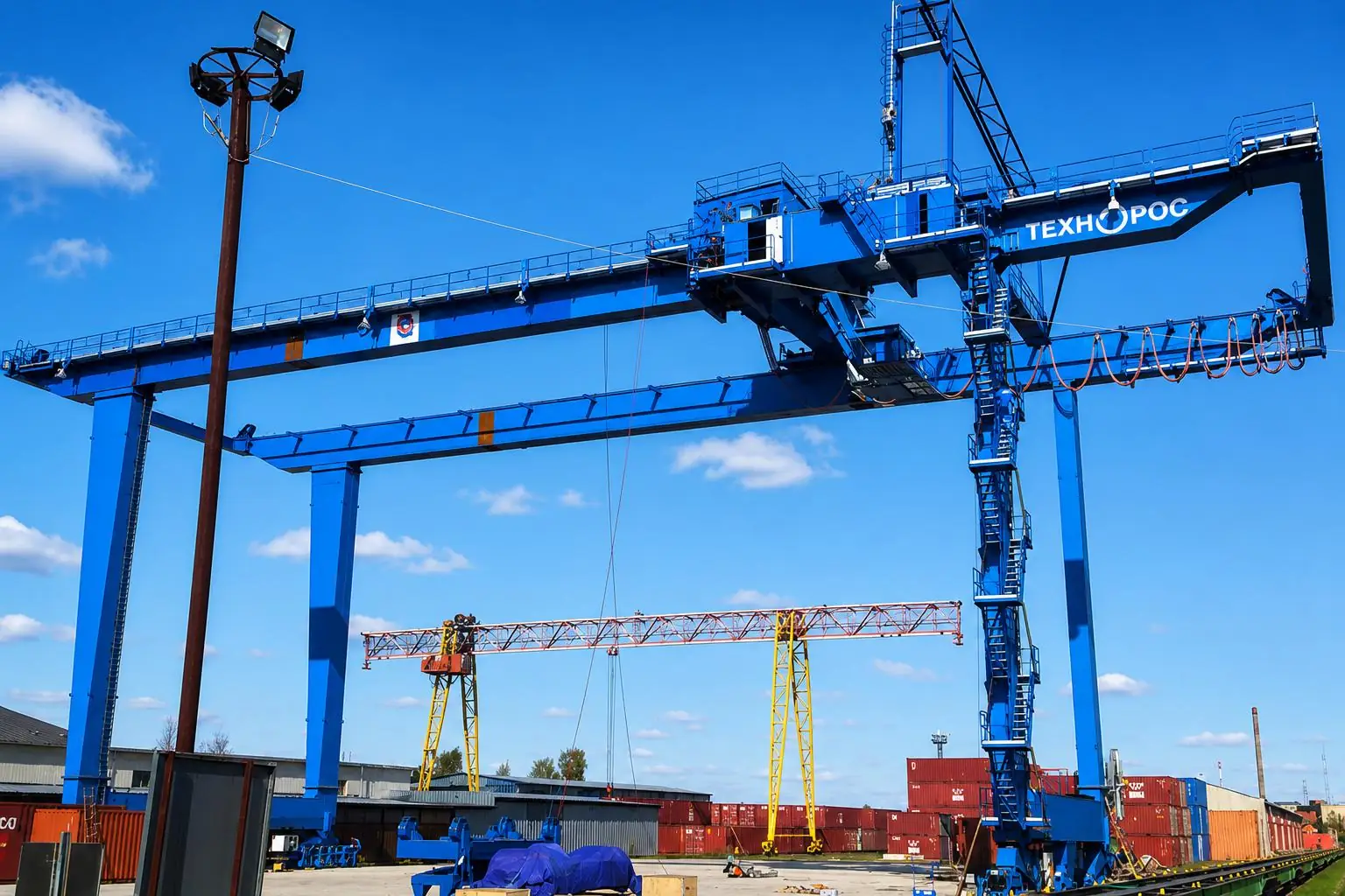
In 50t Cantilever Gantry Cranes, side bay loading refers to the hook being picked, placed or transported outside the two gantry support lines.Typical tasks include loading and unloading trucks, handling steel coils, transferring prefabricated components, and serving adjacent production lines.The side span describes the working area, which does not mean that the equipment can be pulled sideways, dragged sideways, or let the lifting weight exceed the specified trolley operating boundary.
When the trolley enters the cantilever, the vertical reaction force borne by the near-side outriggers and wheels increases, and the far-side reaction force decreases.The resulting control problem may be the maximum wheel pressure on the near side, or it may be the unloading of the far side wheel.The strength of the beam meets the requirements, and it cannot individually prove that the side span operation is feasible; the local bearing of the structure, the stability of the whole machine and the track foundation must be verified under the same working conditions.
Load Transfer from the Cantilever to the Supporting Legs
The lifting weight first enters the lifting mechanism and the trolley frame, and then is passed from the trolley wheel to the main beam.The main beam is connected by beam legs to distribute the action to the outriggers on both sides, the lower beam and the cart wheels pass the reaction force to the track, and finally enter the track beam, concrete foundation and foundation.The stiffness of any link is obviously insufficient, which will change the theoretical load distribution.
When the load crosses the near-side support line, the near-side reaction force will rise and the far-side reaction force will decrease.Due to simultaneous unloading on the far side, the increase in the reaction force on the near side may even exceed the new lifting itself.When calculating the total reaction force, the weight of the main beam, outriggers, trolley and other components must be superimposed.Then, according to the spatial stiffness of the door frame, the end beam structure and the equalization mechanism, the reaction force of the support line needs to be further distributed to each wheel, rather than simply dividing by the number of wheels.
Overturning Moment and Wheel Load Verification
The lifting weight of the side span forms a overturning torque relative to the support line on the near side, and the weight of the span and other weights located within the support range provide a stabilizing effect.If the calculated reaction force of a support drops to zero, the wheel is in a critical state of unloading; if the reaction force is negative, it means that the original contact hypothesis has failed, and ordinary wheels cannot transmit the required downward binding force to the track.
The stability check should also consider the start and brake of large and small cars, operation skew, swing of lifting weight and wind action.The horizontal force forms an additional overturning torque through its acting height, which will also increase the lateral action of the outriggers, rims, and track.The state of the equipment under shutdown wind conditions is different from that of the equipment under on-load operation conditions, and a combination should be established according to the respective allowable parking position and windproof device.
The wheel pressure result needs to give the maximum and minimum values at the same time.The maximum wheel pressure is used to check the bearing capacity of the wheels, rails, track beams and foundations, and the minimum wheel pressure is used to judge contact and stability.Track height difference, foundation difference settlement and manufacturing errors may make the actual wheel pressure more uneven than the ideal rigid model, so the allowable deviation of civil construction must be consistent with the mechanical design assumptions.
Side Bay Loading Scenarios to Evaluate
Full-load conditions in the outermost allowable position usually produce a larger bending moment at the root of the cantilever, but other positions cannot be ignored as a result.Partial loads combined with operation or braking may control certain structural details; partial loads will still occur when the no-load trolley is parked at the end of the cantilever; the weight of the spreader needs to be included in all relevant working conditions according to its true attribution.
If the control system allows lifting, trolley operation and cart operation to occur at the same time, the calculation combination should reflect this operation.If the system prohibits certain actions from being concurrent through interlocking, the restrictions must be implemented in the control logic and operation files.Environmental working conditions should also distinguish between the working state and the non-working state, so as to avoid blindly superimposing extreme values that will not appear at the same time, and to avoid missing the actual allowable concurrent effects.
Worked Engineering Example: Evaluating a 50t Cantilever Gantry Crane
Establishing the Preliminary Design Conditions
The following scenario is used to illustrate the preliminary evaluation path of 50t Cantilever Gantry Cranes.The project requires a single-sided cantilever to lift the rated load from the transport vehicle, and the vehicle stop is close to the outermost position that the hook is allowed to reach.The weight of the trolley, spreader and cantilever are all known, and the site also gives the main span, track location, basic conditions and required work level.
The engineer first converts the working envelope of the hook into the range of the wheel position of the trolley, and then sorts out the position of the lifting weight, the trolley and the weight of the structure.The cross-section, material, outrigger form and wheel set arrangement of the main beam are entered as preliminary plans.The purpose of this stage is to determine whether the extension scheme is worth entering the detailed design, rather than issuing a conclusion of equipment qualification based on this.
Estimating the Cantilever Root Moment
Preliminary analysis shows that when the trolley is approaching the outer end of the cantilever, the lifting weight and the weight of the trolley jointly increase the bending moment of the root, while the weight of the cantilever itself forms a continuous additional effect.The outermost position can be regarded as an important working condition, but the engineer should also check the local effects of each wheel of the trolley when it passes through the cross-section in turn, and compare the working conditions of the fully loaded, partially loaded and no-load trolley.
After entering the formal design, the lifting weight, trolley, spreader and structural self-weight need to be modeled separately, and then the corresponding power coefficient and combination rules are applied in accordance with the selected criteria.Simply combining all the weights and enlarging them uniformly may mask the different properties of various functions, and may not correctly reflect the operating, braking, and environmental conditions.
Checking Girder Strength and Deflection
The preliminary strength review first looks at the overall bending and shear, and then checks the pressure area of the trolley wheel, the pressure plate, the root stiffening structure and the welding connection.Even if the overall nominal stress is low, local buckling, torsion, or weld stress concentration may still control the design.According to the control problem, you can consider increasing the beam height, adjusting the flange and web thickness, optimizing the stiffening system, or shortening the cantilever.
The deformation review should include the full length of the main beam, the outriggers, and the actual boundary stiffness.Treating the root as completely fixed can only reflect the partial bending of the cantilever, not the complete displacement of the hook.The engineer must also check the relative angle between the main span and the cantilever, as well as the change in the slope of the trolley track when the load moves, and then make a judgment based on the service performance criteria adopted by the project.
Evaluating Wheel Reactions and Side Bay Feasibility
The review of the support reaction force will show that the force of the near wheel set increases and the force of the far wheel set decreases.Engineers need to pay attention to the maximum wheel pressure on the near side and the minimum wheel pressure on the far side at the same time, because the former controls the wheel, track and foundation bearing, while the latter is related to contact and stability.If the far side is close to unloading, the solution requires shortening the extension, adjusting the support geometry, or redistributing the weight of the whole machine.
The reaction force of the support line is not the final single-wheel wheel pressure.The distribution must be continued according to the actual number of wheels, wheel track, balance beam and door frame spatial stiffness, and horizontal effects, dynamic effects, wind and possible uneven support must be added.Only when the maximum wheel pressure, minimum wheel pressure, structural strength, deflection and basic capacity all meet the applicable requirements can the side span scheme be confirmed to be feasible.
Common Design Challenges and How to Address Them
Excessive Cantilever Deflection
When the cantilever is too long, the elevation and horizontal position of the hook will change significantly with the load, and the slope of the trolley track will increase.The solution should first identify the source of deformation: the local bending of the cantilever can be improved by increasing the beam height or the moment of inertia of the cross-section, and the rotation of the main span requires adjusting the overall beam body and the support system. Simply thickening the steel plate at the beam end often has limited effect.
Uneven Wheel Loads and Rail Overloading
The side-span bias load will concentrate on increasing the reaction force of the near-side support.Adding wheels only makes sense if the equalization mechanism can effectively distribute the load, and adjusting the outrigger geometry or expanding the track spacing may improve stability as a whole.Any changes need to be checked simultaneously for track beams, concrete foundations, foundation bearing and settlement, rather than just comparing the rated capacity of the wheels.
Local Buckling and Welded Joint Fatigue
The thin-walled box girder may have partial instability of the flange or web when the nominal stress is not yet high.Stiffeners and diaphragms can improve stability and wheel pressure diffusion, but their ends may also become fatigue-sensitive locations.The weld arrangement should avoid sudden turns in the force flow, and reserve inspection space for the roots, track connections, and cross-section transitions.
Balancing Cantilever Reach Against Structural Cost
Increasing the length of the cantilever will also increase the main beam material, local reinforcement, near-side wheel pressure and basic requirements, and may also require greater driving and braking capabilities.Effective optimization should compare the system-wide cost of each additional coverage distance.If the truck parking line or yard boundary is rearranged to shorten the extension, the project can usually obtain a more reasonable structural weight and maintenance conditions.
Inadequate Allowance for Future Operating Conditions
In the future, increasing the lifting frequency, changing the size of the cargo, replacing the trolley or increasing the spreader will all change the original assumptions.The reserved capacity must be expressed in terms of specific weight, position, speed, and number of cycles.Vague future expansion requirements cannot be translated into reliable calculations. When the later working conditions exceed the boundaries of the original design, the main beam, wheels, track and foundation should be re-verified.
How to Optimize a 50t Cantilever Gantry Crane for Side Bay Operations
- Optimization first starts from the job layout.By putting the center of gravity of the cargo, the size of the spreader, the wheel position of the trolley, the vehicle passage and the safety headroom into the same working envelope, the effective extension distance that is really needed can be determined.Then select the suitable main beam structure to coordinate the beam height, cross-section performance, torsional resistance, manufacturing and transportation restrictions, and maintenance space.
- The structure of the trolley should reduce unnecessary self-weight and hook bias, while maintaining sufficient wheel track and maintenance conditions.The mechanical design should provide the civil construction with the maximum and minimum wheel pressure, horizontal force and combination description under each working condition, while the civil construction design feedback the track support stiffness, allowable deviation and settlement conditions, so that the two sets of models adopt the same boundary.
- Finite element analysis can be used to identify spatial load distribution, cross-section transition, and local stress in the welding area. Simplified beam model and overall balance calculation are suitable for checking the order of magnitude and load path.The two types of methods are checked against each other, which can reduce the misjudgment caused by boundary setting or grid selection.The conclusions of the model must eventually be implemented into manufacturable, detectable, and maintainable structural details.
- The maintenance plan of the 50t Cantilever Gantry Cranes should focus on the cantilever roots, stiffener ends, track welds, wheels and tracks.The inspection frequency should match the actual cycle and environment; when the operation records show that the lifting weight distribution or the operating frequency continues to deviate from the design load spectrum, the fatigue state needs to be re-evaluated, not just to shorten the routine maintenance interval.
- Standards, Testing, and Safety Verification
- The project should first determine the applicable crane design system, such as EN 13001 or the FEM-related requirements stipulated in the contract, and then adopt the applicable steel structure, welding, fatigue and inspection regulations.The expressions of load classification, dynamic coefficient, combination and resistance of different systems may be different. The calculation book should be consistent and indicate the version used and the additional conditions of the project.
- The manufacturing phase requires control of material traceability, welding process, geometry, and non-destructive testing.The inspection and test after the installation is completed should cover the structural status, rated capacity, braking, limit, overload protection and applicable windproof devices.The test load, duration, and eligibility criteria are determined by the adopted standards and project requirements, and a fixed magnification cannot be extended to all equipment.
- A load test can only verify the performance under the specified test state, cannot replace the fatigue calculation, and cannot cover all trolley locations and environmental combinations.The final document should clarify the allowable side span load, hook position, linkage conditions, wind speed boundary and shutdown requirements, so that the calculation model, control system and on-site operation are consistent.
Selecting a 50t Cantilever Gantry Crane Manufacturer
Manufacturers should be able to determine the main span, cantilever, and hook envelope based on site size and logistics processes, rather than just providing a general solution based on 50 t tonnage.The technical data needs to give the load input, structural model, key combination, strength and deflection results, and the maximum and minimum reaction forces of each wheel or wheel set.When the foundation is designed by other units, the interface data must be complete and traceable.
The procurement assessment should also cover the work level, lifting height, operating speed, indoor and outdoor environment, track status and installation restrictions.Qualified customization capabilities are reflected in how these conditions enter the design, and can explain whether the side span allows full load, which actions can be performed at the same time, and which positions are restricted by the control system.
Structural manufacturing, welding quality control, inspection, installation and commissioning, and after-sales support need to form a continuous chain of responsibility.For existing yard or production line renovation projects, on-site measurement, track evaluation and basic review are particularly critical.The complete project delivery is not a table of equipment parameters, but a set of documents that can implement design assumptions into the manufacturing and use stages.
Conclusion
The cantilever design of the 50t Cantilever Gantry Cranes cannot be determined separately by the rated lifting weight and outer elongation.The bending moment and shear force of the root control the overall carrying requirements, the stiffness determines the performance of the hook and track, and the redistribution of the load to the support on both sides controls the maximum wheel pressure, remote unloading and basic requirements.The three types of results must come from the same set of operating conditions and boundary conditions.
A reliable solution begins with accurate site layout, cargo and spreader weight, trolley parameters, operating frequency and environmental conditions.Only by using these data to complete structural calculations, wheel pressure verification, civil construction coordination and inspection planning can the geometric coverage outside the outriggers be transformed into long-term usable side span operation capabilities.