
100t Precast Railway Beam Gantry Cranes: Heavy Wheel Load Sizing for High-Speed Rail
In the construction of high-speed rail bridges and viaducts, the hoisting, transportation and stacking of prefabricated box girders and T-beams is a key process, which is related to progress and safety.The 100-ton railway prefabricated beam gantry crane is the core heavy equipment of the high-speed rail beam yard. The selection and calculation of heavy-duty wheel pressure are the focus of site adaptation, stable foundation, and long-term safe operation.
Many construction units only pay attention to the rated lifting weight of 100 tons in the selection of models, ignoring their own weight, dynamic wheel pressure and site conditions, which can easily cause hidden dangers such as track collapse, foundation settlement, and equipment instability.
This article introduces the crane structure, wheel pressure calculation, high-speed rail selection points and design specifications, provides technical reference for equipment selection and construction design, and answers technical questions such as gantry crane wheel pressure calculation and 100-ton gantry crane maximum wheel pressure.
What Is a 100t Precast Railway Beam Gantry Crane
The 100-ton railway prefabricated beam gantry crane is a heavy-duty lifting equipment for railway infrastructure, which can complete the hoisting, transshipment, stacking and assembly of prefabricated beams within 100 tons.Most of the equipment is rail-walking double-beam and double-trolley structure, which has stable operation and accurate positioning, and is suitable for outdoor heavy-duty beam yard operations.
The mainstream configuration is 50t+50t double hoist synchronous lifting, evenly sharing the load, and suitable for long prefabricated beams.However, 100 tons is only the rated reference, not the design limit. Engineering design requires comprehensive accounting of self-weight, dynamic load, wind load and orbital deviation.
Core application scenarios
The 100-ton railway prefabricated beam gantry crane is specifically adapted to the needs of railway infrastructure operations in all scenarios, and its core application scope covers:
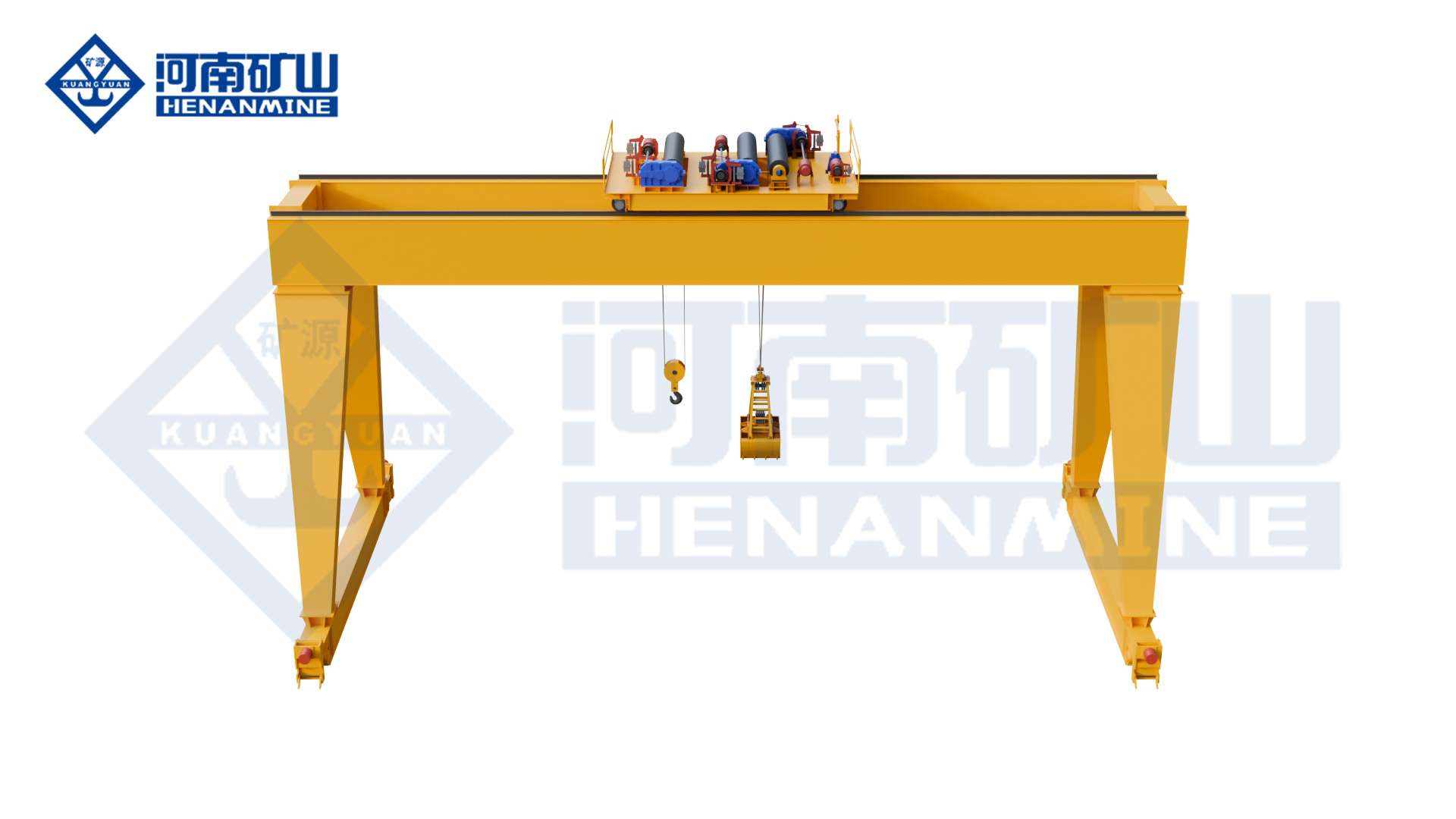
- Main beam and outrigger structure: Generally, box-shaped main beam or truss main beam are used, with a combination of rigid outriggers and flexible outriggers.This structure can effectively control the deflection of the main beam under heavy-duty operations, resist the deformation caused by alternating loads, and meet the strength requirements of long-term high-frequency hoisting.
- Lifting mechanism: equipped with a single trolley or dual synchronous trolley system, often using a combination of double hoists for hoisting, with special prefabricated beam spreaders.The synchronous operation of the double lifting points can disperse the force of the beam body and prevent distortion and deformation of the long beam during hoisting.
- Cart walking mechanism: it consists of a rail-type end trolley and multiple sets of wheel train, which is responsible for the longitudinal movement of the crane along the track.The multi-wheeled trolley design can disperse the wheel pressure and reduce the load on the track and foundation.
- Trolley operating mechanism: the lifting trolley moves laterally along the main beam, flexibly adjusting the position of the lifting point, and adapting to the lifting of prefabricated beams of different lengths and different lifting point positions.
- Electrical control system: equipped with frequency conversion drive system and synchronous control system, it supports two modes of cab operation and wireless remote control.Frequency conversion and speed regulation achieve smooth start and stop, avoid impact loads during hoisting, and ensure the safety of beam hoisting.
- Track walking base: The standard crane track supporting structure is adopted, and the load is distributed through multiple rounds of combined management, and the maximum wheel pressure of a single wheel is controlled from the source of the structure to meet the requirements of outdoor heavy-duty continuous operation.
The equipment can be adapted to the outdoor open-air, dusty, and complex construction environment, effectively reducing the cost of off-site transportation of prefabricated beams, and greatly improving the construction efficiency of high-speed rail projects.
Equipment standard configuration structure
The 100-ton railway prefabricated beam gantry crane adopts a heavy-duty reinforced structure, and the core configuration takes into account strength, stiffness and stability. The specific composition is as follows:
- Main beam and outrigger structure: box-type or truss-type main beam is selected, with rigid and flexible reinforced outriggers, which can effectively resist structural deformation under heavy loads, and control the deflection of the main beam within the allowable range of the specification to meet the requirements of long-term cycle heavy-duty operations.
- Lifting mechanism: equipped with a single trolley or a double synchronous trolley, with a double synchronous hoist system, a special spreader for prefabricated beams and a beam lifting device, the load is evenly distributed when hoisting the long-span beam body to avoid the local stress concentration of the beam body.
- Cart walking mechanism: it adopts a rail-type end trolley and a multi-wheel structure to support the smooth movement of the whole machine along the longitudinal direction of the track, dispersing the total load to multiple wheels, and reducing the wheel pressure of a single wheel.
- Trolley operating mechanism: the lifting trolley can be accurately displaced laterally along the main beam, and the position of the lifting point can be flexibly adjusted to adapt to the lifting conditions of prefabricated beams with different beam lengths and different lifting point arrangements.
- Electrical control system: integrated frequency conversion speed control system (VFD) and synchronous control system, supporting two operating modes of cab operation and wireless remote control, to achieve precise speed regulation, smooth start and stop, and reduce hoisting impact.
- Track walking base: adopts a standardized track adaptation structure and relies on the load-sharing design of multiple wheel sets to control the maximum single-wheel wheel pressure from the structural level to protect the track and the lower foundation.
Understanding Heavy Wheel Loads in Gantry Crane Design
Wheel pressure is the core parameter of 100-ton prefabricated beam gantry crane design, site foundation construction, and track selection, which directly determines the operating stability and engineering safety of equipment, and is the top priority of high-speed rail lifting engineering design.
The core definition of wheel pressure
Wheel pressure refers to the vertical pressure generated by the crane's walking wheels (wheel sets/trolleys) on the track. It is the core basis for track selection and foundation bearing capacity accounting. It is mainly divided into two categories.:
- Maximum wheel pressure: The maximum vertical pressure that a single wheel can withstand under the most unfavorable working conditions of the equipment (trolley partial load, full load hoisting, dynamic impact) is the control parameter of the engineering design.;
- Static wheel pressure: the value of the wheel pressure when the equipment is stationary and there is no dynamic impact, which is only affected by the gravity load;
- Dynamic wheel pressure: The actual wheel pressure after superimposed hoisting acceleration, equipment walking braking, vibration shock, and wind load is usually 1.1-1.3 times the static wheel pressure.
During crane operation, the load will be redistributed according to the position of the trolley, the position of the lifting point, and the state of the track. The wheel pressure of each wheel is not evenly distributed, and the local partial load will greatly increase the pressure of a single wheel.
Core factors affecting wheel pressure
The wheel pressure value of a 100-ton gantry crane is not a fixed value and is affected by multiple parameters. The core factors are as follows:
- Rated lifting weight: The rated lifting load of 100 tons is the most basic source of load for wheel pressure calculation.Under the extreme working conditions of prefabricated beam hoisting, the beam body load will be directly transmitted to the trolley, the main beam, and the outriggers, and ultimately act on the walking wheels, which is one of the core factors that determine the maximum wheel pressure level.
- Equipment weight: The weight of the crane, plus the weight of the trolley, spreader, hanging beam device and other ancillary components, together constitute the main part of the static wheel pressure.It is easy for many engineering calculations to ignore self-weight, but the weight of heavy-duty gantry cranes often accounts for a high proportion of the total load, which has a significant impact on the wheel pressure results.
- Span and outrigger structure: The larger the span of the crane, the longer the force transmission path between the outriggers; if the stiffness of the rigid outrigger and the flexible outrigger is inconsistent, the force transmission will deviate, and the uneven distribution of wheel pressure will be more prominent. The phenomenon is more prominent, and the one-sided wheels are more prone to load concentration.
- Trolley and load position: When the lifting trolley moves with the prefabricated beam to one side of the outrigger and approaches the limit position, the load center is biased to this side, and the wheel pressure on that side will increase sharply.This is also the control condition that must be used when calculating the maximum wheel pressure in the project.
- The number and arrangement of wheel sets: Under the premise that the total load remains the same, the number of wheels is rationally increased, and the wheel track and trolley arrangement are optimized at the same time, which can effectively distribute the total load, reduce the wheel pressure on a single wheel, and make the load distribution of the whole machine more uniform.
- Start-stop acceleration and braking force: Acceleration and braking during the movement of the cart and the traverse of the cart will produce inertial forces, which are superimposed on the static load, directly increasing the instantaneous dynamic wheel pressure.The faster the start-stop speed, the more obvious the inertial impact, and the greater the wheel pressure fluctuation.
- Environmental load: The wind load of open-air operations, the uneven foundation settlement caused by the long-term use of the site, and the deviation between the level and height of the track laying will all change the force state of each wheel, further exacerbating the uneven distribution of wheel pressure, and even causing individual wheels to overload.
Maximum wheel pressure and average wheel pressure
The average wheel pressure is the theoretical value of the total load evenly distributed to all wheels. It is only suitable for rough estimation and must not be used in engineering design.The maximum wheel pressure is the only control standard for the track and basic design of high-speed rail projects.
During the hoisting of prefabricated beams and the walking of equipment, the partial load of the trolley, the offset of the beam weight, and the uneven track will all cause the load to be concentrated, and the wheel pressure of a single wheel will be much higher than the average value.If the track and foundation are designed according to the average wheel pressure, problems such as local track collapse, cracking of concrete foundation, and uneven foundation settlement will occur, which directly affect construction safety and equipment service life.
Why High-Speed Rail Projects Require Careful Wheel Load Sizing
Compared with ordinary highway and municipal projects, the construction of high-speed rail prefabricated beams has extremely high requirements for the wheel pressure control of gantry cranes. The core stems from the high standards, high precision and high safety requirements of high-speed rail projects.
Characteristics of heavy-duty operation of prefabricated beams
The prefabricated box girders and T-beams of high-speed rail are large in size and have concentrated self-weight. The weight of the single beam is close to the rated load of the equipment, and the construction process requires frequent hoisting, precise alignment, and fine-tuning.Under long-term high-frequency and heavy-duty operations, the stability of the wheel pressure value directly determines the hoisting accuracy of the equipment, and avoids construction quality problems such as beam offset and alignment deviation.
Track and foundation bearing capacity requirements
The track and concrete foundation of the high-speed rail beam yard are customized designs, and there are strict standards for the bearing capacity, flatness, and anchoring strength of the special track for P50/P60 cranes and the reinforced concrete foundation.If the wheel pressure exceeds the design limits of the track and foundation, track deformation, loose bolts, and foundation settlement will occur, which will directly damage the construction base of the beam field and affect long-term construction safety.
Guarantee the walking stability of the equipment
The 100-ton gantry crane needs to carry a long-span prefabricated beam to walk. The beam body itself is prone to shaking, superimposed on the outdoor wind load and the track is slightly uneven, which is prone to the risk of equipment instability.Accurate wheel pressure ratio and uniform load distribution can effectively reduce the walking offset of the equipment and the swing of the beam body, and ensure the overall stability of the heavy-duty walking process.
Key Design Parameters for a 100t Precast Beam Gantry Crane
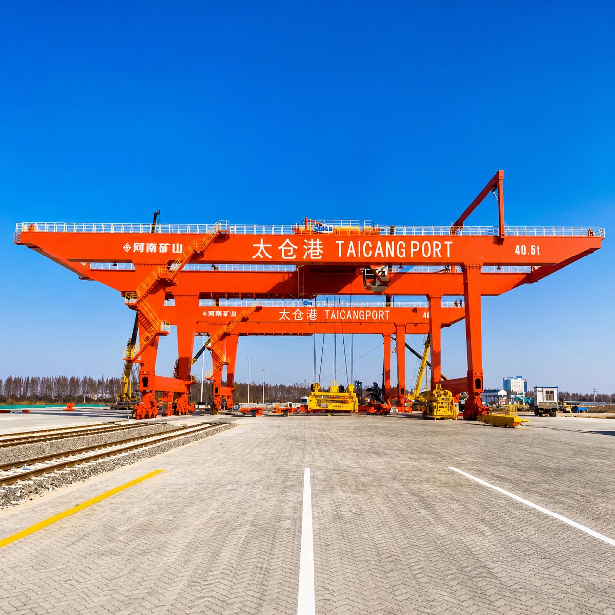
The 100-ton gantry crane adapted to the high-speed rail project needs to optimize the core parameters around wheel pressure control, safety and stability, and working condition adaptation. The key design indicators are as follows:
Lifting capacity and safety margin
The rated lifting weight is 100 tons, and the equipment is designed to reserve not less than 1.25 times the safety margin, which can cover the deviation of the beam weight, the weight of the spreader, and various temporary additional loads.The whole machine is equipped with an overload protection system to eliminate overload operations from the hardware level and meet the requirements of Class A safety specifications for high-speed rail projects.
Equipment span and lifting height
The applicable span range of conventional beam yards is 18–50m, which can be customized in combination with the layout of the site; the lifting height is 10–20m, which can meet the requirements of the spatial net distance between the layered storage of prefabricated beams and the high-level erection, and avoid component interference during hoisting operations.
Wheel and track matching design
High-strength forged alloy wheels are used to harden the tread, wear-resistant and compression-resistant; the wheel pressure is dispersed by increasing the number of wheel sets and optimizing the spacing of wheel tracks; and the special track for QU series cranes is matched to achieve accurate wheel-rail matching and minimize the problem of local load concentration.
Walking speed and drive system
The heavy-duty walking speed is set to 5–20m/min to meet the needs of low-speed precise alignment; the whole machine is equipped with a frequency conversion synchronous multi-drive system to ensure the synchronous start, stop, acceleration and deceleration of the outriggers on both sides, effectively preventing the uneven distribution of wheel pressure caused by walking deviation.
Main structure design
The main beam adopts a high-stiffness box-shaped structure to strictly control the deflection of heavy loads; the legs are strengthened with compression and torsional design to adapt to long-term cyclic heavy loads; the overall structure is optimized for fatigue resistance and adapted to high-frequency operating conditions of high-speed rail projects to eliminate wheel pressure offset caused by structural deformation.
Precast Railway Beam Conditions That Influence Crane Sizing
The wheel pressure design and selection of the 100-ton gantry crane must match the actual working conditions of the prefabricated beam of the project. The core influencing conditions include:
- Beam body parameters: the length of the prefabricated beam, the cross-section size, the weight distribution, the position of the lifting point and the height of the center of gravity directly affect the load transfer method during hoisting.The center of gravity and force points of different types of high-speed rail box girders and T-beams are obviously different, and improper design of the lifting points can easily cause the beam body to distort and tilt the hoisting.
- On-site operating conditions: the layout of beam storage in the beam yard, the stacking form and the average daily hoisting frequency determine the working level and long-term heavy-duty cycle strength of the 100-ton gantry crane.High-frequency hoisting produces alternating loads, which affect the dynamic changes of wheel pressure and the fatigue life of equipment. It is an important reference for wheel pressure verification and structure optimization.
- Site and track conditions: The bearing capacity and track flatness of the ground foundation of the beam site will change the state of the wheel force. Once there is a height difference or the foundation is weak, it is easy to produce partial loads, causing local wheel pressure to exceed the standard.
Safety Systems for Heavy-Duty Railway Beam Gantry Cranes
For high-speed rail outdoor heavy-duty operation scenarios, 100-ton prefabricated beam gantry cranes must be equipped with a complete set of safety systems to avoid abnormal wheel pressure and equipment instability risks.:
- Overload protection system: collect and continuously monitor the load of hoisting operations in real time, automatically trigger the protection action when the load exceeds the rated limit, cut off the lifting power in time, and eliminate the phenomenon of overload from the source to avoid a sharp increase in wheel pressure due to excessive load, and prevent overload damage to the wheels, tracks and foundations.
- Stroke limit switch: set the limit position protection for the traverse of the trolley, the lifting height, and the walking of the trolley respectively.Once it is run to the boundary position, it can automatically stop, prevent the equipment from running offside, avoid a large shift in the lifting center of gravity and cause the partial load to get out of control, and control the maximum wheel pressure not to exceed the design value.
- Emergency braking system: In the event of emergency working conditions such as sudden failure and abnormal force, it supports one-key shutdown and locking, quickly fixing the position of the crane and the whole machine, limiting further changes in the load, and avoiding the risk of wheel pressure mutation and instability caused by sudden load impact.
- Anti-collision system: scan the surrounding space in real time, monitor the distance between the equipment and the equipment and the beam field structure, give early warning and slow down and brake in advance, avoid hard collisions and produce instantaneous impact loads, and prevent the impact from causing the local wheel pressure to soar instantly.
- Walking deviation monitoring: continuously collect data on the walking trajectory of the cart, cooperate with the drive system to correct the running direction in real time, suppress the deviation of the cart, prevent the force on one side of the outrigger from increasing, and avoid the uneven distribution of wheel pressure caused by track offset and rail gnawing.
- Windproof anchoring device: For the open-air operating environment of the beam yard, the whole machine can be locked by the anchoring device in windy weather to resist the additional horizontal force and overturning torque generated by the lateral wind load, reduce the increase in unilateral wheel pressure caused by the wind load, and ensure the stability of the equipment in strong winds.
- Synchronous lifting control system: accurately control the lifting action of the double trolley, maintain the same lifting speed and displacement height on both sides, ensure the balance of force during the lifting of the prefabricated beam, avoid the tilt of the beam body and partial load, and maintain the stability of the wheel pressure of the whole machine.
- Regular inspection mechanism: Establish a normalized inspection plan, regularly detect the degree of wheel wear, track deformation, and fatigue damage of the main steel structure, investigate diseases in time, and ensure that the wheel pressure parameters are stable in the design allowable range for a long time.
Common Mistakes When Selecting a 100t Railway Gantry Crane
Combined with the construction experience of high-speed rail projects, high-frequency misunderstandings in the selection of equipment in the industry are also the core problem that leads to the failure of wheel pressure design.:
- Only rated load selection: Only refer to the rated lifting weight of 100 tons when selecting the type, ignoring the crane's own weight, dynamic load, wind load and other additional forces, resulting in distortion of the wheel pressure calculation results.
- Ignore the influence of equipment weight: The weight of the gantry crane itself accounts for a high proportion of the total load, which is the core parameter of the wheel pressure calculation, but it is often missed by designers during the project planning stage.
- Misuse of average wheel pressure instead of maximum wheel pressure: simply design the track and foundation according to the average wheel pressure evenly distributed by the load, without considering the extreme partial load conditions such as trolley bias, there are safety risks.
- Underestimate the dynamic impact load: the wheel pressure calculation does not include the dynamic amplification coefficient caused by equipment start-stop, operating vibration, and wind load, resulting in the track and basic design values are too small.
- Mismatch of wheel and rail parameters: The actual wheel pressure of the crane does not match the bearing capacity and track specifications of the existing track on the site, and long-term operation can easily cause track deformation and damage.
- Ignore the deviation of the beam weight center of gravity: The center of gravity is offset when the prefabricated beam is hoisted, which will cause the wheel pressure on one side of the equipment to exceed the limit, causing safety risks such as partial load and abnormal structural force.
- Unreserved expansion margin: The plan only adapts to the current beam type parameters, and there is no reserved design margin, making it difficult to cope with subsequent production capacity increase, beam type replacement and other construction adjustment needs.
How to Specify a 100t Gantry Crane for a High-Speed Rail Project
In order to facilitate the precise selection of projects and the customization of docking manufacturers, a verification list of special selection parameters for high-speed rail projects is organized to cover all core design indicators.:
| Key Parameters | Required Project Information |
| Rated Lifting Capacity | Standard 100 t; dual-hoist synchronized configuration available per project requirements |
| Girder Parameters | Max. girder self-weight, length, cross-section dimensions, and center of gravity |
| Crane Span | Rail center-to-center distance, tailored to precast yard layout and working range |
| Lifting Height | Max. hook height to satisfy clearance for stacking and girder erection |
| Working Duty Class | Heavy-duty class A5–A7 selected according to operating frequency |
| Travel Speed | Empty/loaded travel speed matched to on-site positioning accuracy requirements |
| Wheel Set Configuration | Number of wheels, wheelbase, and wheel-set arrangement |
| Maximum Wheel Load | Project-specific engineered dynamic maximum wheel load value |
| Rail Specification | Existing rail model or custom rail design parameters |
| Foundation Conditions | Site bearing capacity and concrete foundation design parameters |
| Power Supply | Site voltage and frequency; compatible with diesel generator backup system |
| Operating Environment | Outdoor wind speed, temperature, dust, and other working conditions |
Conclusion
The 100-ton railway prefabricated beam gantry crane is a heavy-duty special equipment suitable for high-speed rail construction.In addition to the rated lifting weight, the selection also needs to focus on self-weight, dynamic load, wind load, beam weight, wheel configuration and maximum wheel pressure, and match the track and basic plan based on the calculation results.
In the actual design, the gantry structure, wheel set and safety control system should be configured in a targeted manner in accordance with the construction site, operation mode, operation frequency and safety requirements to ensure that the equipment and the track foundation are coordinated and matched.
Henan Mine Crane can provide customized design and manufacturing solutions for 100-ton gantry cranes based on the load parameters, site conditions and construction requirements of railway prefabricated beam projects, and perform engineering calculations for key parameters such as maximum wheel pressure to provide matching lifting equipment support for high-speed rail prefabricated beam hoisting construction.